
Probe card assembly

a technology of probe card and assembly, which is applied in the direction of printed circuit assembly, non-electric welding apparatus, printed element electric connection formation, etc., can solve the problems of difficult to achieve reliable mechanical connection between free-standing resilient (spring) contact elements mounted to the terminals of space transformers, the use of separate interposer components in probe card assemblies can also be undesirable, and the die is “good” (full function), etc., to achieve convenient control of impedance, easy demountability, and effective shield

Inactive Publication Date: 2005-02-17
FORMFACTOR INC
View PDF73 Cites 18 Cited by
  • Summary
  • Abstract
  • Description
  • Claims
  • Application Information

AI Technical Summary

Benefits of technology

[0072] An additional advantage of the present invention is that connections made with the interconnection elements of the present invention are readily demountable. Soldering, to effect the interconnection to a terminal of an electronic component is optional, but is generally not preferred at a system level.
[0073] According to an aspect of the invention, techniques are described for making interconnection elements having controlled impedance. These techniques generally involve coating (e.g., electrophoretically) a conductive core or an entire composite interconnection element with a dielectric material (insulating layer), and overcoating the dielectric material with an outer layer of a conductive material. By grounding the outer conductive material layer, the resulting interconnection element can effectively be shielded, and its impedance can readily be controlled. (See also FIG. 10K of the PARENT CASE.)
[0074] According to an aspect of the invention, interconnection elements can be pre-fabricated as individual units, for later attachment to electronic components. Various techniques for accomplishing this objective are set forth herein. Although not specifically covered in this document, it is deemed to be relatively straightforward to fabricate a machine that will handle the mounting of a plurality of individual interconnection elements to a substrate or, alternatively, suspending a plurality of individual interconnection elements in an elastomer, or on a support substrate.
[0075] It should clearly be understood that the composite interconnection element of the present invention differs dramatically from interconnection elements of the prior art which have been coated to enhance their electrical conductivity characteristics or to enhance their resistance to corrosion.
[0076] The overcoating of the present invention is specifically intended to substantially enhance anchoring of the interconnection element to a terminal of an electronic component and / or to impart desired resilient characteristics to the resulting composite interconnection element. Stresses (contact forces) are directed to portions of the interconnection elements which are specifically intended to absorb the stresses.
[0077] It should also be appreciated that the present invention provides essentially a new technique for making spring structures. Generally, the operative structure of the resulting spring is a product of plating, rather than of bending and shaping. This opens the door to using a wide variety of materials to establish the spring shape, and a variety of “friendly” processes for attaching the “falsework” of the core to electronic components. The overcoating functions as a “superstructure” over the “falsework” of the core, both of which terms have their origins in the field of civil engineering.

Problems solved by technology

Among the problems associated with using a space transformer component in a probe card assembly is that of matching the coefficients of thermal expansion of the space transformer to that of the wafer under test (WUT).
Furthermore, in some instances, depending on the materials (e.g., ceramic layers, terminals, etc.) and processes employed in the manufacture of the space transformer component, it can be difficult to achieve a reliable mechanical connection between free-standing resilient (spring) contact elements mounted to the terminals of the space transformer under the stresses encountered when making repeated pressure connections to terminals of other electronic components, such as would be encountered when probing a sequence of WUTs or a series of die sites on a one or more WUTs.
The use of a separate interposer component in a probe card assembly can also be undesirable.
In practice, however, certain physical defects in the wafer itself and certain defects in the processing of the wafer inevitably lead to some of the dies being “good” (fully-functional) and some of the dies being “bad” (non-functional).
Certain difficulties are inherent in any technique for probing semiconductor dies.
This ring-shape layout makes it difficult, and in some cases impossible, to probe a plurality of unsingulated semiconductor dies (multiple sites) on a wafer, especially when the bond pads of each semiconductor die are arranged in other than two linear arrays along two opposite edges of the semiconductor die.
As a general proposition, the higher the yield strength of a material, the more difficult it will be to work with (e.g., punch, bend, etc.).
Such “hostile” processes are generally not desirable (and often not feasible) in the context of certain relatively “fragile” electronic components such as semiconductor devices.
However, both solder and gold are relatively soft (low yield strength) materials which will not function well as spring elements.
A subtle problem associated with interconnection elements, including spring contact elements, is that, often, the terminals of an electronic component are not perfectly coplanar.

Method used


Image

  • Probe card assembly
  • Probe card assembly
  • Probe card assembly

Examples


Embodiment Construction

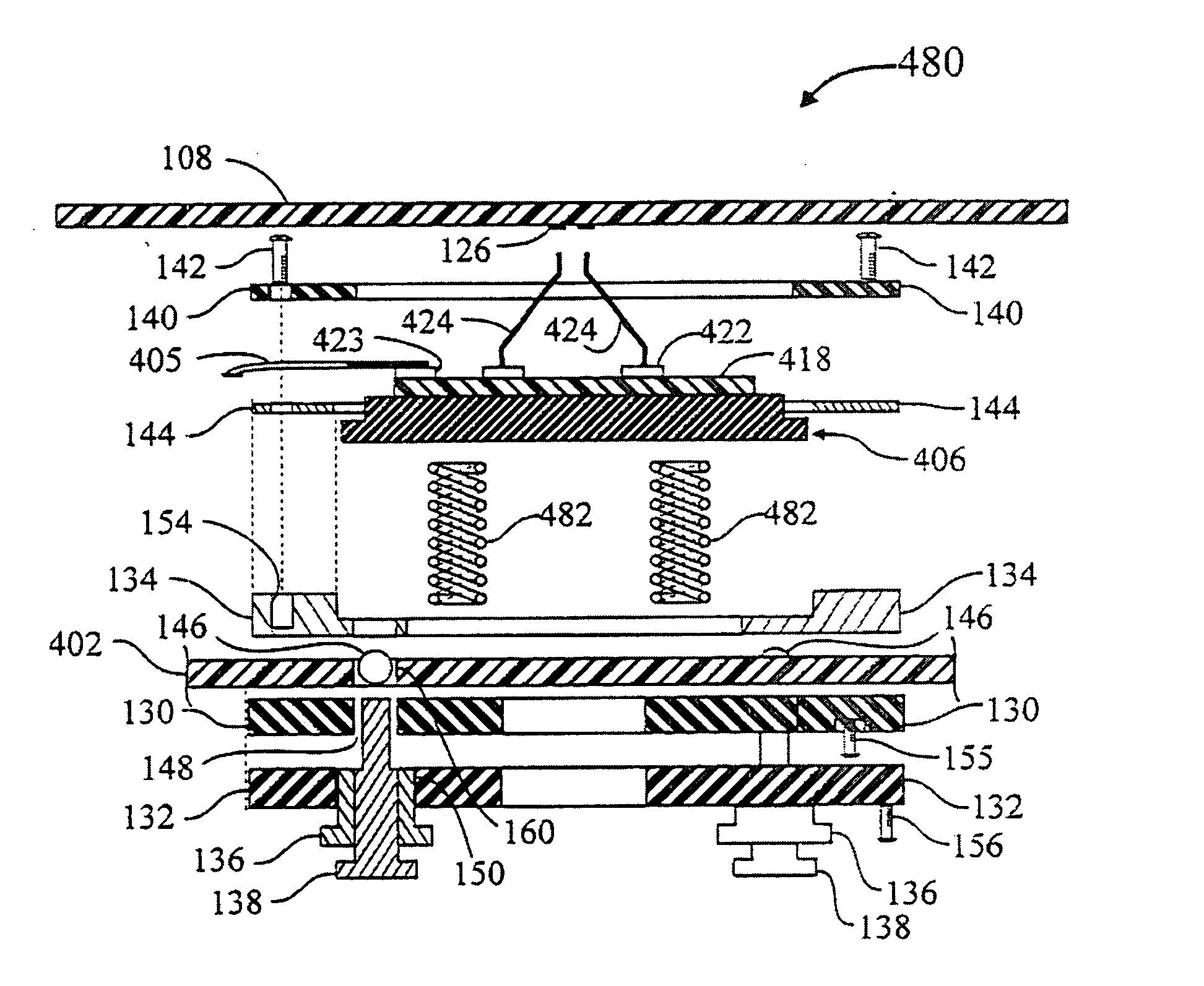
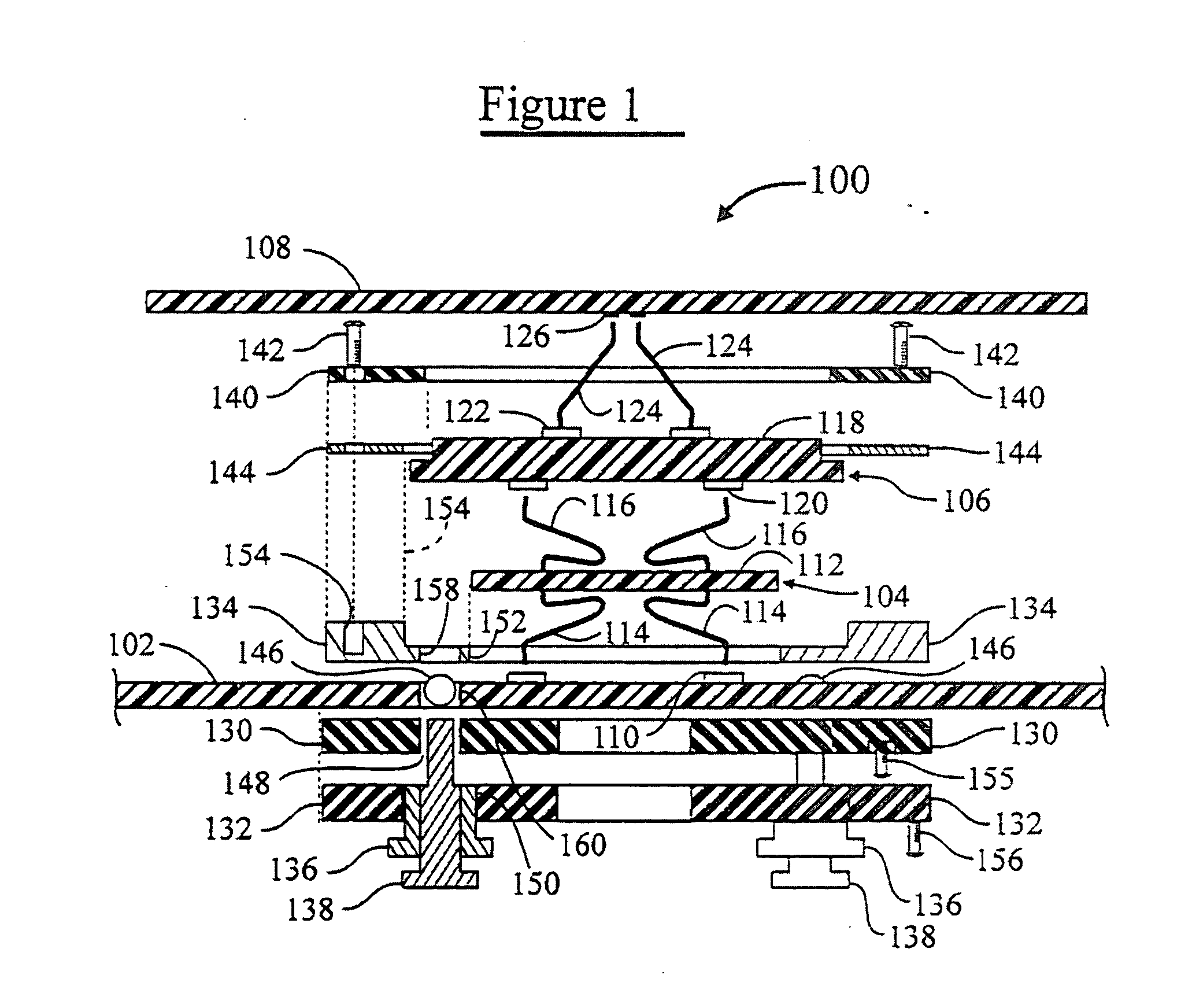
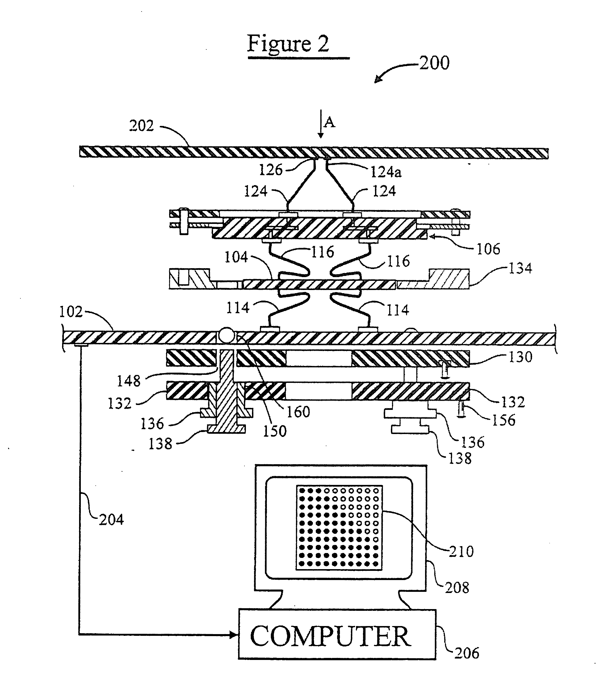
[0057] This patent application is directed to probe card assemblies, components thereof, and methods of using same. As will be evident from the description that follows, the use of resilient (spring) contact structures to effect pressure connections to terminals of an electronic component is essential. The resilient contact structures are suitably (but not necessarily) implemented as “composite interconnection elements”, such as have been described in the disclosure of the aforementioned U.S. patent application Ser. No. 08 / 452,255 (“PARENT CASE”), incorporated by reference herein.

[0058] According to an aspect of the invention, the probe elements (resilient contact structures extending from the top surface of the space transformer component) are preferably formed as “composite interconnection elements” which are fabricated directly upon the terminals of the space transformer component of the probe card assembly. The “composite” (multilayer), interconnection element is fabricated by ...


PUM

PropertyMeasurementUnit
lengthaaaaaaaaaa
lengthaaaaaaaaaa
diameteraaaaaaaaaa

Abstract

In a probe card assembly, a series of probe elements can be arrayed on a silicon space transformer. The silicon space transformer can be fabricated with an array of primary contacts in a very tight pitch, comparable to the pitch of a semiconductor device. One preferred primary contact is a resilient spring contact. Conductive elements in the space transformer are routed to second contacts at a more relaxed pitch. In one preferred embodiment, the second contacts are suitable for directly attaching a ribbon cable, which in turn can be connected to provide selective connection to each primary contact. The silicon space transformer is mounted in a fixture that provides for resilient connection to a wafer or device to be tested. This fixture can be adjusted to planarize the primary contacts with the plane of a support probe card board.

Description

CROSS-REFERENCE TO RELATED APPLICATIONS [0001] This patent application is a continuation-in-part of commonly-owned, copending U.S. Provisional Patent Application No. 60 / 040,983 filed 17 Mar. 1997 by Khandros and Sporck (status: pending) [0002] which is a continuation-in-part of commonly-owned, copending U.S. patent application Ser. No. 08 / 554,902 filed 09 Nov. 1995 by Eldridge, Grube, Khandros and Mathieu (status: pending), and its counterpart PCT patent application number PCT / US95 / 14844 filed 13 Nov. 1995 (published as WO96 / 15458), [0003] which are continuations-in-part of commonly-owned, copending U.S. patent application Ser. No. 08 / 452,255 (hereinafter “PARENT CASE”), filed 26 May 1995 by Eldridge, Grube, Khandros and Mathieu (status: pending), and its counterpart PCT patent application number PCT / US95 / 14909 filed 13 Nov. 1995 (published as WO96 / 17378), [0004] which are continuations-in-part of commonly-owned, copending U.S. patent application Ser. No. 08 / 340,144 filed 15 Nov. 19...

Claims


Application Information

Patent Timeline
Patent Type & Authority Applications(United States)
IPC IPC(8): B23K1/00B23K20/00C23C18/16C25D5/08C25D5/22C25D7/12C25D21/02G01R1/04G01R1/067G01R1/073G01R31/28H01L21/00H01L21/48H01L21/56H01L21/60H01L21/603H01L21/66H01L23/48H01L23/485H01L23/49H01L23/498H01L25/065H01L25/16H05K1/14H05K3/20H05K3/30H05K3/32H05K3/34H05K3/36H05K3/40H05K7/10
CPCH05K3/368H05K3/4015H05K3/4092H05K7/1069H05K2201/0397H05K2201/068H05K2201/1031H05K2201/10318H05K2201/10378H05K2201/10719H05K2201/10734H05K2201/10757H05K2201/10878H05K2201/10909H05K2201/10946B23K1/0016B23K20/004B23K2201/40C25D5/08C25D5/22C25D21/02G01R1/06711G01R1/07342G01R1/07364G01R1/07378G01R31/2886H01L21/4853H01L21/4889H01L21/563H01L21/76897H01L22/20H01L23/49811H01L24/11H01L24/72H01L24/81H01L25/0652H01L25/16H01L2224/1134H01L2224/13099H01L2224/16145H01L2224/49109H01L2224/73203H01L2224/81801H01L2224/85201H01L2225/0651H01L2225/06527H01L2225/06555H01L2225/06572H01L2924/01002H01L2924/01005H01L2924/01015H01L2924/01074H01L2924/01078H01L2924/01079H01L2924/01082H01L2924/014H01L2924/14H01L2924/1532H01L2924/3011H01L2924/3025H05K1/141H05K3/20H05K3/308H05K3/326H05K3/3421H05K3/3426H01L24/13H01L24/49H01R12/52H01L2924/00013H01L2924/01006H01L2924/01033H01L2924/01045H01L2224/45144H01L2924/10253H01L2924/0001H01L2924/00014H01L2924/00H01L2224/48H01L24/45H01L2224/45014H01L2924/15787B23K2101/40Y02P70/50C25D5/605H01L2224/05599H01L2924/206
Inventor KHANDROS, IGOR Y.SPORCK, A. NICHOLASELDRIDGE, BENJAMIN N.
Owner FORMFACTOR INC
Learn More