Circuit, apparatus and method for obtaining a lock state value

a technology of lock state value and apparatus, applied in the direction of electrical apparatus, pulse automatic control, etc., can solve the problems of time and complexity, expensive test equipment, and inability to readily obtain expensive test equipmen

Inactive Publication Date: 2005-02-17
RAMBUS INC
View PDF18 Cites 25 Cited by
  • Summary
  • Abstract
  • Description
  • Claims
  • Application Information

AI Technical Summary

Problems solved by technology

Since a PLL's phase and frequency are typically controlled by precise analog signals, expensive test equipment may be used to obtain the state of the PLL either by extracting this precise analog information directly, or by inferring it via precise measurements of the timing characteristics of the ...

Method used


Image

  • Circuit, apparatus and method for obtaining a lock state value
  • Circuit, apparatus and method for obtaining a lock state value
  • Circuit, apparatus and method for obtaining a lock state value

Examples


Embodiment Construction

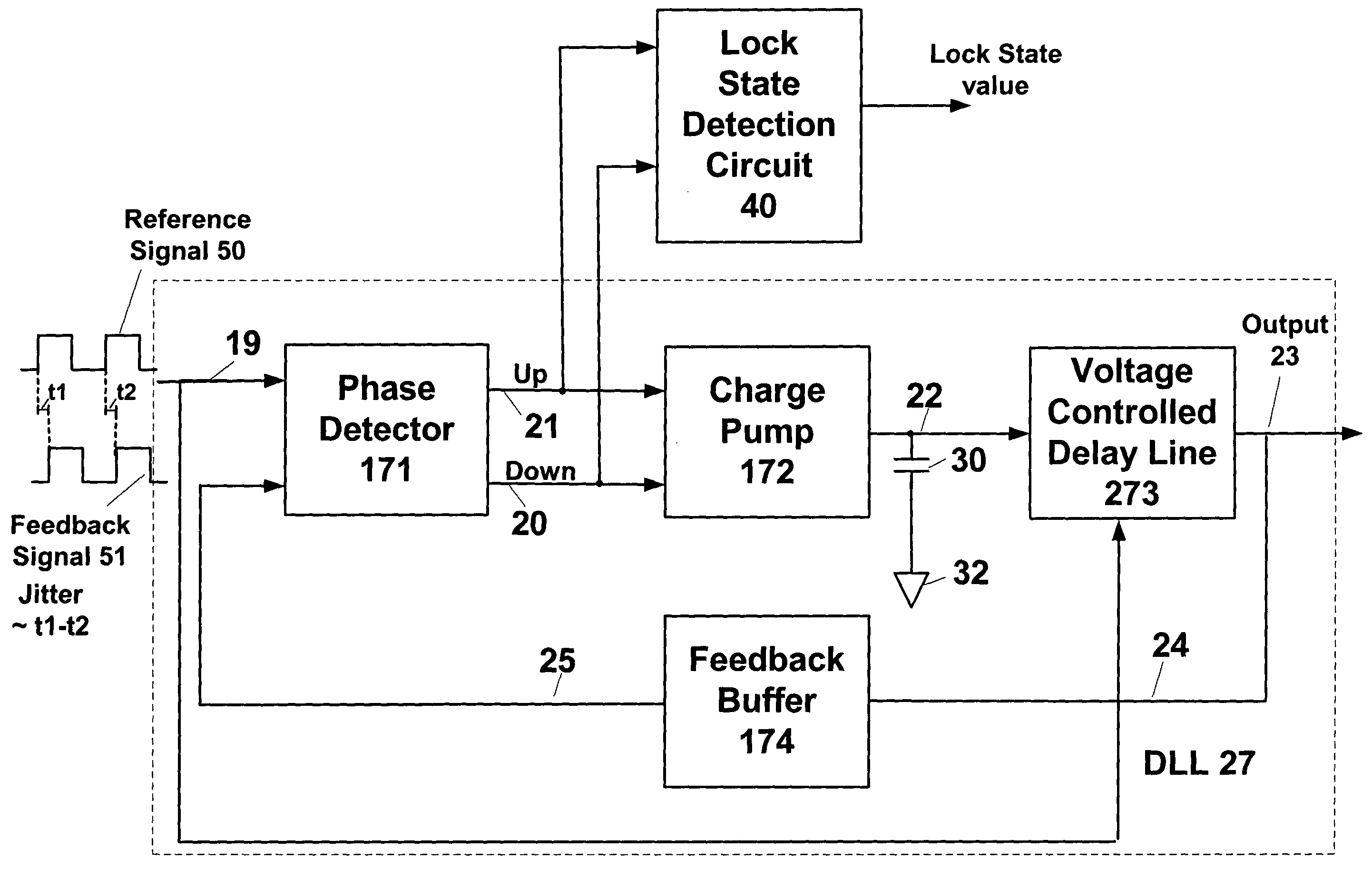
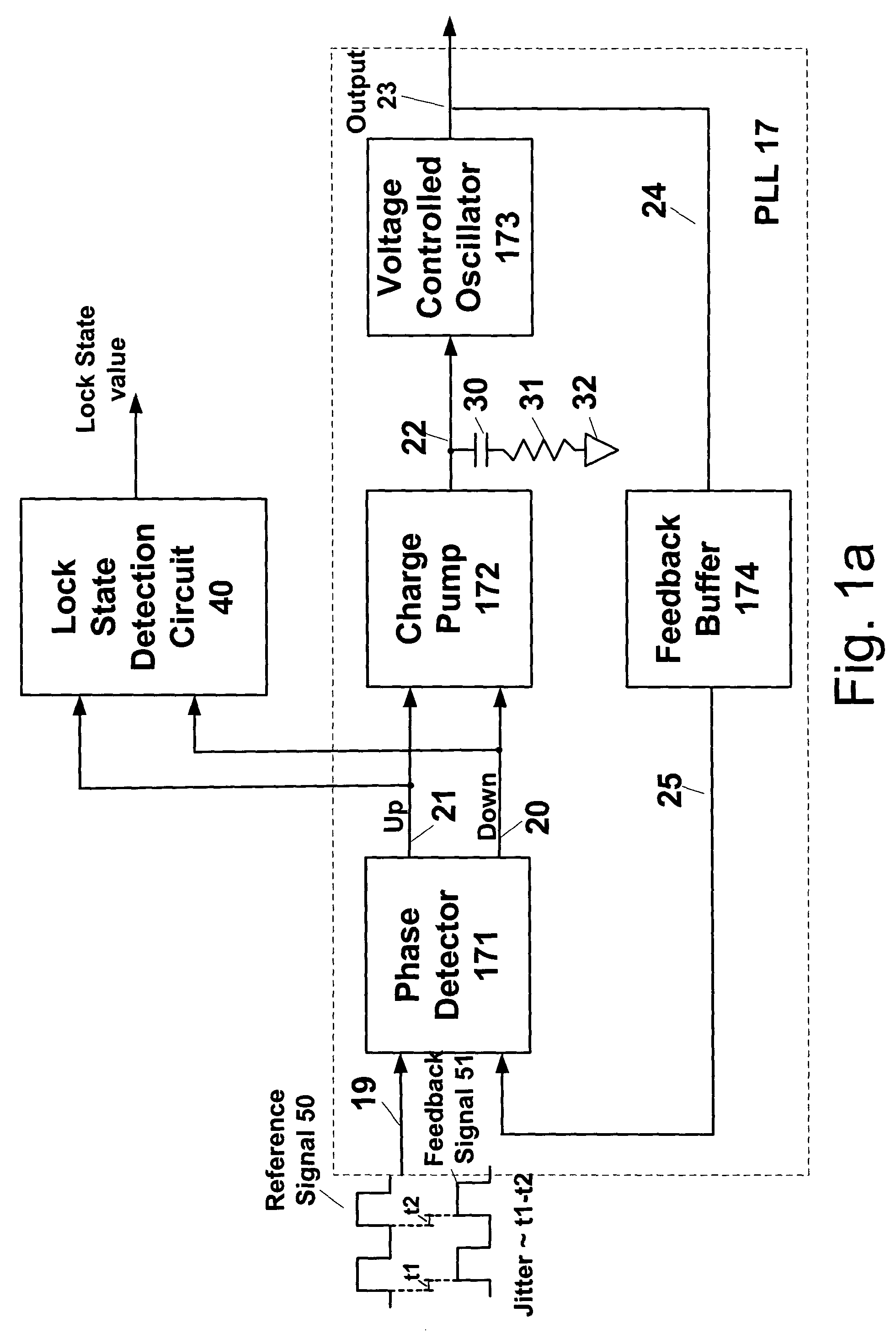
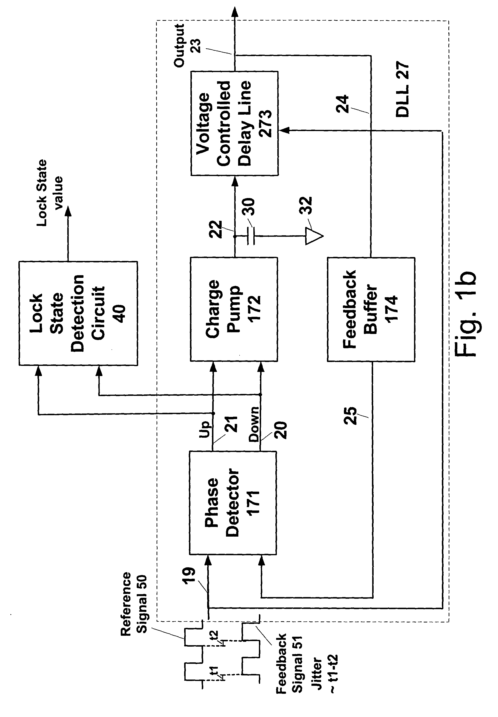
[0015] Embodiments of the present invention allow a circuit, apparatus and method to provide a lock state value representing an amount of time a phase alignment circuit (“PAC”) circuit, such as a PLL or DLL, is tracking or locked to an incoming reference signal during a predetermined period of time. In other words, a digital lock state value is generated which represents the quantity of dynamic phase offset (i.e., jitter) between a PAC's reference input and its feedback input during a predetermined period of time. For example, FIG. 1a illustrates jitter between two edges of a reference signal 50 as it is compared to a feedback signal 51: the cycle-to-cycle difference between t1 and t2 is the “jitter” quantity of interest.

[0016] In embodiments of the present invention, a lock state detection circuit is coupled to either a PLL or DLL. In an embodiment of the present invention, a lock state detection circuit includes a novel phase detection circuit and a counter circuit. The phase det...


PUM


Abstract

A circuit, apparatus and method provides a lock state value representing an amount of time a phase alignment circuit (“PAC”), such as a PLL or DLL, is tracking or locked to an incoming reference signal for a predetermined period of time. In an embodiment of the present invention, a lock state detection circuit is coupled to a lock loop circuit and includes a phase detection circuit and a counter circuit. The phase detection circuit includes a phase detector and delay elements that are coupled to the PAC phase detector. The phase detector outputs a lock state sample value of the PAC. In an embodiment of the present invention, the PAC is locked when a stream of alternating lock state sample values, logical 1's and 0's, are output from the phase detector. The counter circuit includes a flip-flop, an XOR gate and counter for obtaining a lock state value for a predetermined period of time.

Description

FIELD OF THE INVENTION [0001] The present invention relates to obtaining performance data, and in particular, information regarding the operational performance of a phase-alignment circuit. BACKGROUND OF INVENTION [0002] A phase-alignment circuit (“PAC”), such as a Phase Lock Loop (“PLL”) or a Delay Lock Loop (“DLL”), is an electronic circuit which generates an output signal that has a well-controlled relationship in phase and frequency to an input signal. [0003] Phase-alignment circuits are used in a variety of electronic devices. For example, a PLL may be used for clock synthesis in a multi-purpose processor. In another example, a PAC may be used in point-to-point communication systems, including serial and parallel systems, where one PAC generates a sampling clock at the receiver while another PAC generates a transmit clock at the output driver of the transmitter. [0004] In testing or troubleshooting a phase-alignment circuit such as a PLL, it may be desirable to determine the st...

Claims


Application Information

Patent Timeline
IPC IPC(8): H03L7/06H03L7/089H03L7/095
CPCH03L7/095H03L7/0891
Inventor BEST, SCOTT C.
Owner RAMBUS INC
Why Eureka
Try Eureka