
Sample element qualification

a technology of sample element and qualification, applied in the field of analyte detection, can solve the problems of stripping and detection system suffering, limited performance,

Inactive Publication Date: 2005-02-17
OPTISCAN BIOMEDICAL
View PDF76 Cites 177 Cited by
  • Summary
  • Abstract
  • Description
  • Claims
  • Application Information

AI Technical Summary

Problems solved by technology

These test strips and detection systems suffer from a variety of problems and also have limited performance.

Method used


Image

  • Sample element qualification
  • Sample element qualification
  • Sample element qualification

Examples


Embodiment Construction

Although certain preferred embodiments and examples are disclosed below, it will be understood by those skilled in the art that the invention extends beyond the specifically disclosed embodiments to other alternative embodiments and / or uses of the invention and obvious modifications and equivalents thereof. Thus it is intended that the scope of the invention herein disclosed should not be limited by the particular disclosed embodiments described below. In any method or process disclosed herein, the acts or operations making up the method / process may be performed in any suitable sequence, and are not necessarily limited to any particular disclosed sequence. For purposes of contrasting various embodiments with the prior art, certain aspects and advantages of these embodiments are described where appropriate herein. Of course, it is to be understood that not necessarily all such aspects or advantages may be achieved in accordance with any particular embodiment. Thus, for example, it s...


PUM

PropertyMeasurementUnit
wavelengthsaaaaaaaaaa
diameteraaaaaaaaaa

Abstract

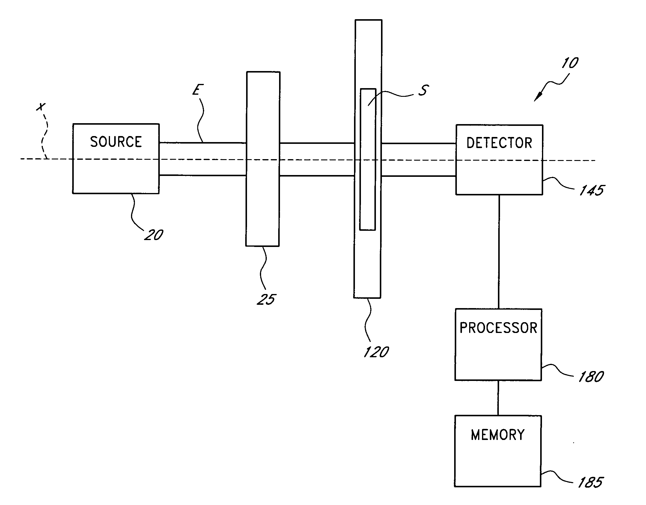
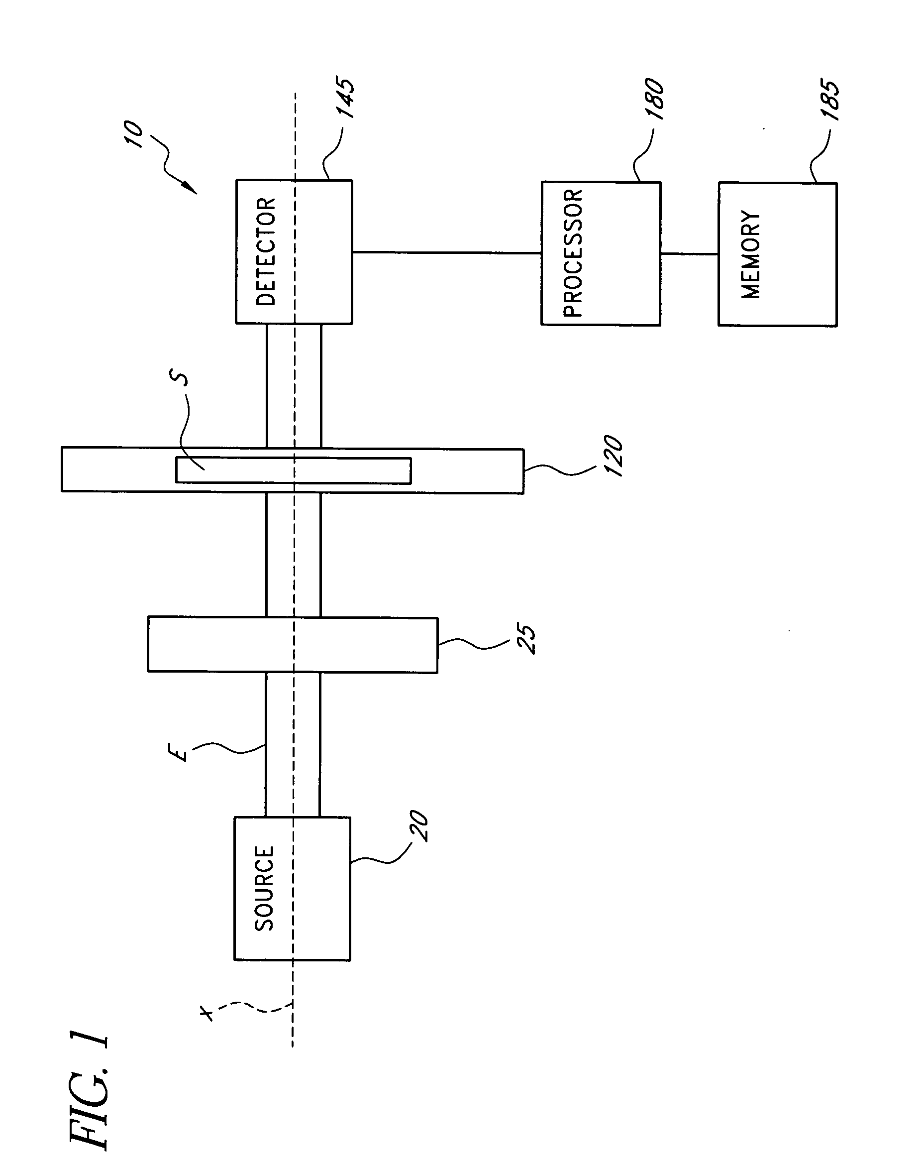
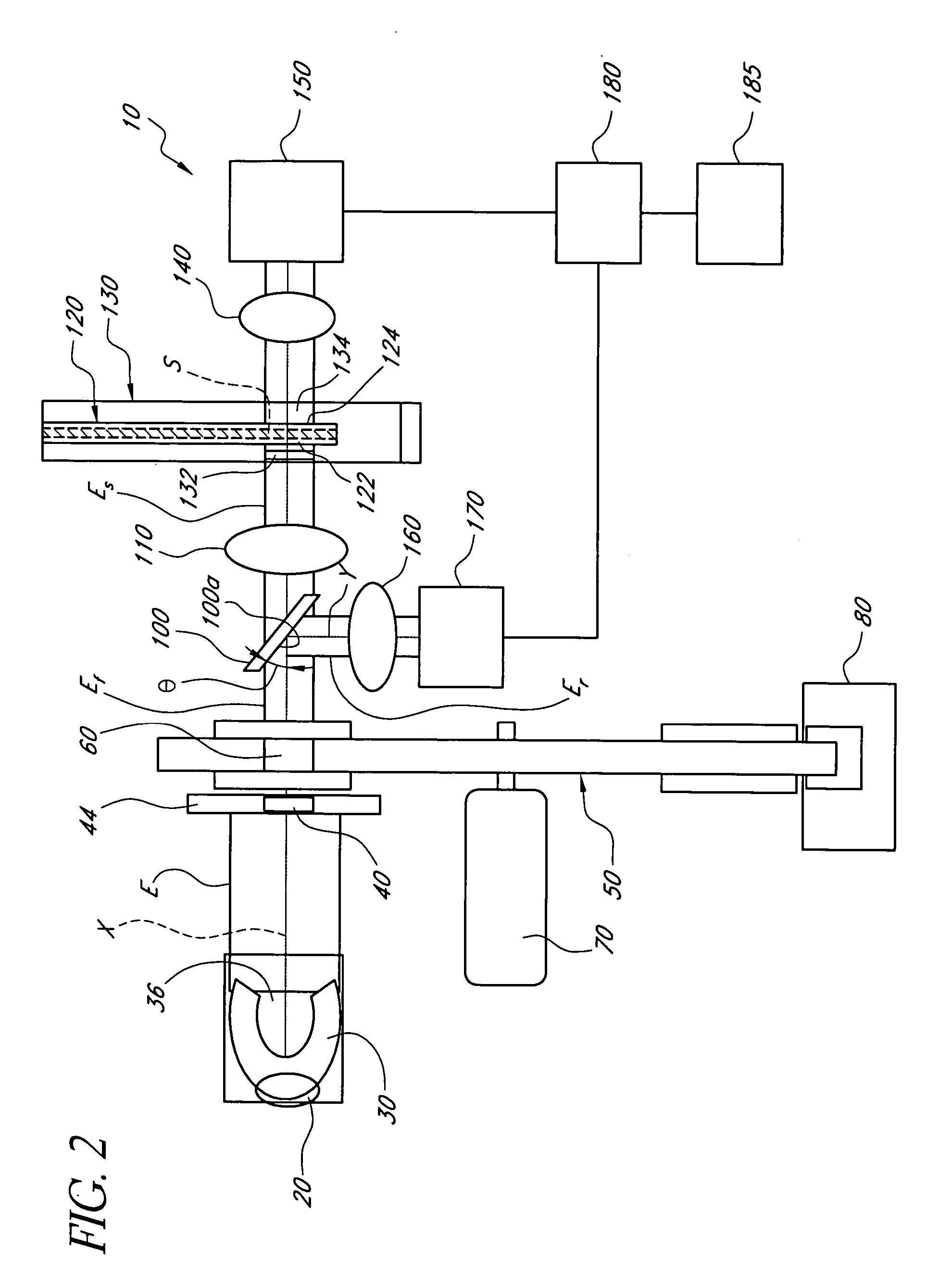
A sample element includes first and second substantially parallel faces separated by an intermediate member. The parallel faces and the intermediate member at least partially define a sample chamber configured to hold a volume of fluid. The sample element further includes an optical path extending through the parallel faces and the intermediate member, such that electromagnetic radiation can propagate through the sample chamber. The sample element further includes an identifying compound disposed within or on at least one of the parallel faces. The identifying compound has at least one indexed optical absorbance feature, such that spectral analysis of electromagnetic radiation propagated through the sample chamber yields the indexed optical absorbance feature. Detection of the indexed optical absorbance feature in electromagnetic radiation propagated through the sample chamber indicates to an analyte detection system whether the sample element is configured for use with the analyte detection system.

Description

FIELD OF THE INVENTION The present invention relates generally to analyte detection in a material sample, and specifically to qualification of a sample element for use with a particular analyte detection system. BACKGROUND OF THE INVENTION Millions of diabetics draw samples of bodily fluid such as blood on a daily basis to monitor the level of glucose in their bloodstream. A small test strip is often employed to hold the sample for analysis by a suitable analyte detection system. These test strips and detection systems suffer from a variety of problems and also have limited performance. SUMMARY OF THE INVENTION In accordance with embodiments described herein, a sample element comprises first and second substantially parallel faces separated by an intermediate member. The parallel faces and the intermediate member at least partially define a sample chamber configured to hold a volume of fluid. The sample element further comprises an optical path extending through the parallel face...

Claims


Application Information

Patent Timeline
Patent Type & Authority Applications(United States)
IPC IPC(8): G01N21/03G01N21/59G01N21/86G01N35/00
CPCG01N21/03G01N21/5907G01N21/8483G01N2035/00782G01N2035/00752G01N2035/00762G01N2035/00772G01N35/00732
Inventor BRAIG, JAMES R.WITTE, KENNETH G.HARTSTEIN, PHILIP C.LI, KEN I.RULE, PETER
Owner OPTISCAN BIOMEDICAL
Learn More