
Method and system for communications channel delay asymmetry compensation using global positioning systems

Active Publication Date: 2005-02-17
GENERAL ELECTRIC CO
View PDF9 Cites 37 Cited by
  • Summary
  • Abstract
  • Description
  • Claims
  • Application Information

AI Technical Summary

Benefits of technology

[0007] In another aspect, a system for compensating for communications channel delay asymmetry in a current differential protection system includes a first algorithm for determining an apparent sampling clock offset for a communications channel, the apparent sampling clock offset between a first sampling clock and a second sampling clock configured within the current differential protection system. A second algorithm is used for determining an apparent global positioning system (GPS) clock offset for the communications channel, the apparent GPS clock offset between a plurality of GPS time stamps corresponding to said first and said second sampling clocks. A mechanism for computing a compensated clock offset subtracts the apparent GPS clock offset from the apparent sampling clock offset so as to cancel out a channel asymmetry component of deviation in the apparent GPS and sampling clock offsets.

Problems solved by technology

The application of an analog line differential scheme over pilot wires was limited to a maximum distance of about 8-10 kilometers, due to several factors such as pilot wire capacitance resistance, extraneously induced voltages (e.g., ground potential rise), etc.
Generally, such measurements are only somewhat synchronized because of difficulty in accurately synchronizing sampling clocks physically separated by large distances.
Conventional uses of digital communications to synchronize sampling clocks at remote locations have accuracies limited by uncertainties in the message delivery time.
In particular, digital communications can have different delays in different directions between a pair of locations, which leads to an error in clock synchronization.

Method used


Image

  • Method and system for communications channel delay asymmetry compensation using global positioning systems
  • Method and system for communications channel delay asymmetry compensation using global positioning systems
  • Method and system for communications channel delay asymmetry compensation using global positioning systems

Examples


Embodiment Construction

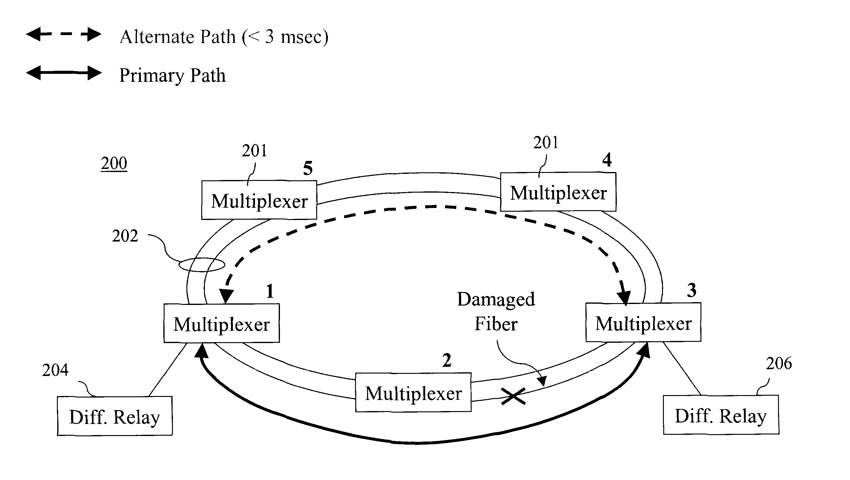
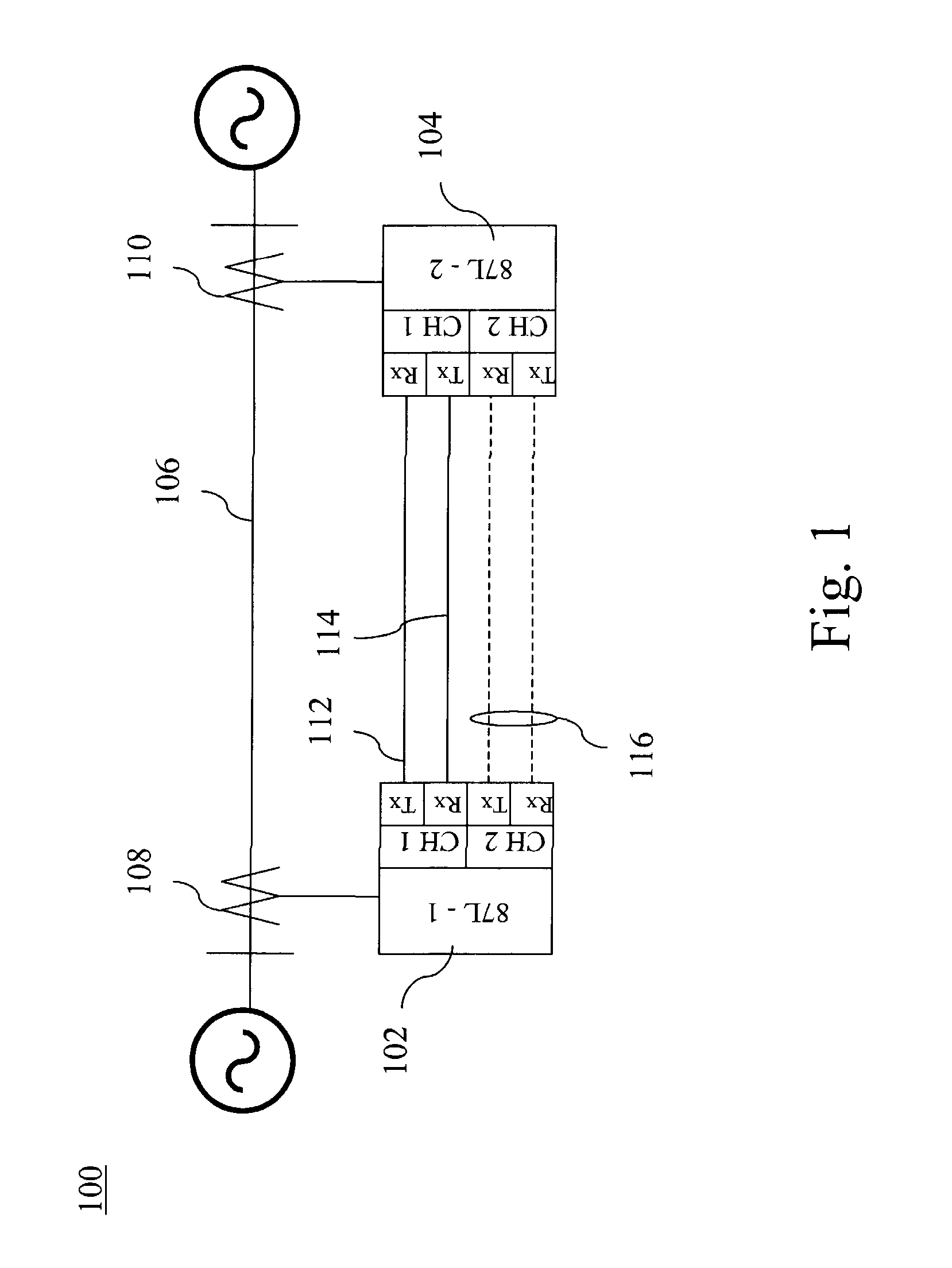
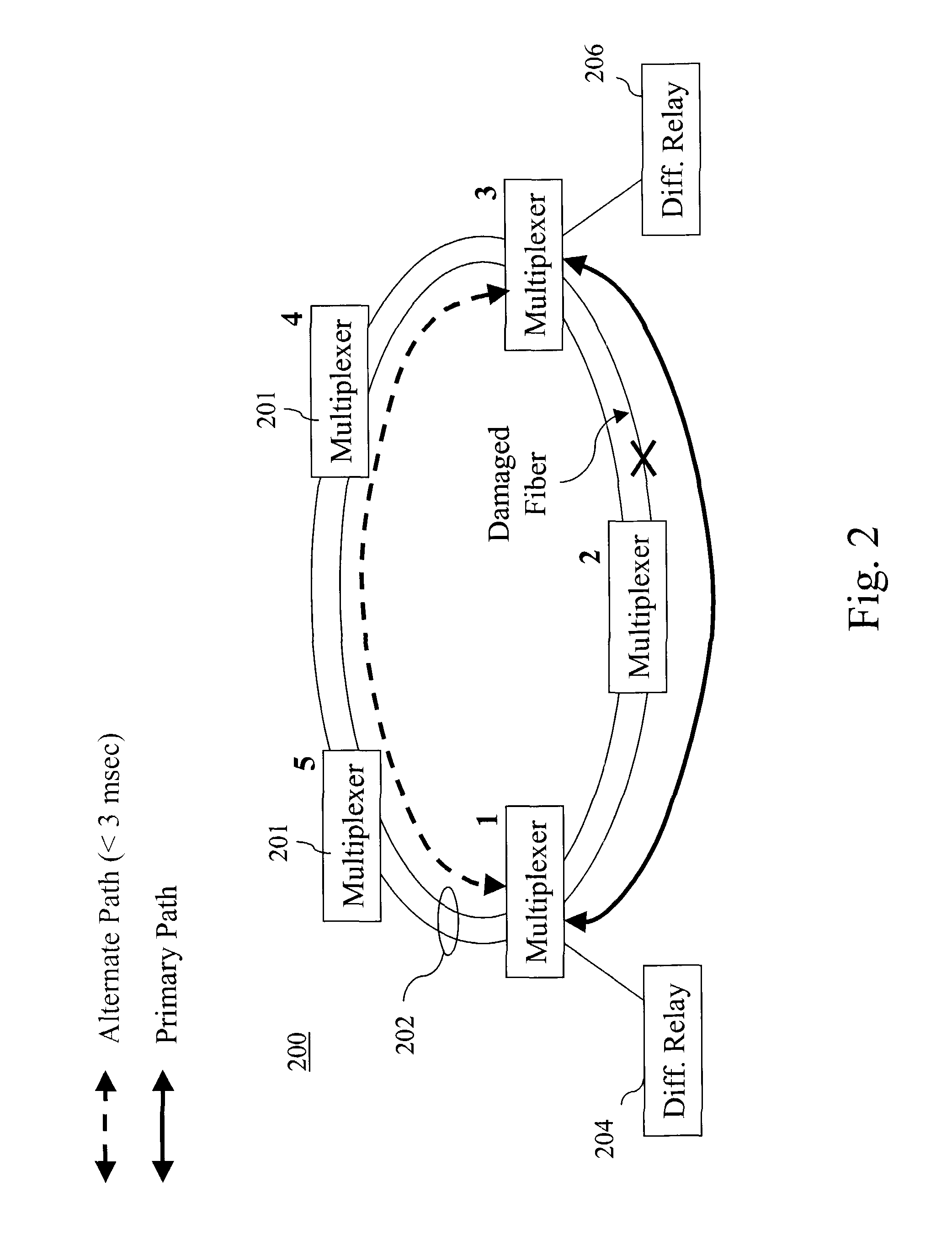
[0013] Disclosed herein is a method and system for communications channel delay asymmetry compensation using global positioning system measurements. Briefly stated, a differential clock offset calculation utilizes two methods for computing clock offset between terminals over a communications link. The first method computes the apparent sampling clock offset from a communications exchange of sampling clock time stamps. The computed offset is equal to the actual offset, plus an error equal to one half of the channel asymmetry. The second method is identical to the first method, except that the time stamps that are exchanged are taken from a global positioning system (GPS) synchronized clock. In this case, the apparent clock offset computed from the second method is equal to one half of the channel asymmetry. The net clock offset is then computed differentially by subtracting the apparent GPS offset from the apparent local clock offset. Thereby, close synchronization is achieved, notwi...


PUM


Abstract

A method for compensating for communications channel delay asymmetry in a current differential protection system includes determining an apparent sampling clock offset for a communications channel, the apparent sampling clock offset between a first sampling clock and a second sampling clock configured within the current differential protection system. An apparent global positioning system (GPS) clock offset is determined for the communications channel, the apparent GPS clock offset between a plurality of GPS time stamps corresponding to the first and said second sampling clocks. A compensated clock offset is determined by subtracting the apparent GPS clock offset from the apparent sampling clock offset so as to cancel out a channel asymmetry component of deviation in the apparent GPS and sampling clock off-sets.

Description

CROSS REFERENCE TO RELATED APPLICATIONS [0001] This application claims the benefit of United States Provisional Application No. 60 / 481,083, filed Jul. 11, 2003 the contents of which are incorporated by reference herein in their entirety.BACKGROUND OF THE INVENTION [0002] The present disclosure relates generally to clock synchronization of current differential systems and, more particularly, to a method and system for communications channel delay asymmetry compensation using global positioning system measurements. [0003] In recent years, there has been an increased interest in the application of line differential relays to very long power transmission lines by utilities all over the world. This renewed attention to this technique is due, in large part, to the availability of digital differential relays operating over high-speed digital communication channels. The basic operating principle of current differential relaying is to calculate the difference between the currents entering an...

Claims


Application Information

Patent Timeline
IPC IPC(8): H02H7/26H04J3/06
CPCH02H7/261H04J3/0644H04J2203/006H04J3/14H04J3/0682H02H3/302
Inventor PREMERLANI, WILLIAM JKASZTENNY, BOGDANVOLOH, ILIA
Owner GENERAL ELECTRIC CO
Learn More