
Apparatus and methods for estimating and compensating sampling clock offset

a sampling clock and compensation method technology, applied in multi-frequency code systems, multiplex communication, orthogonal multiplexes, etc., can solve the problems of high system performance, high complexity of ofdm-uwb system design, and prohibitive ml phase tracking approach, etc., to achieve high interference resistance and low complexity

Active Publication Date: 2010-11-30
WIPRO LTD
View PDF3 Cites 1 Cited by
  • Summary
  • Abstract
  • Description
  • Claims
  • Application Information

AI Technical Summary

Benefits of technology

The proposed method provides robust, low-complexity, and cost-effective SCO estimation and compensation, maintaining high system performance even under low SNR conditions, as demonstrated by effective tracking of both integer and fractional SCO portions and negligible frame error rate performance loss.

Problems solved by technology

The extremely wide-band processing has brought a lot of challenges to the OFDM-UWB system design, especially to the design of some crucial receiving modules such as the symbol timing, the carrier frequency offset (CFO) and sampling clock offset (SCO) compensation, as well as the channel frequency response (CFR) estimation.
The SCO issue is caused by the sampling clock frequency mismatch between the transmitter and the receiver.
Since the UWB device operates at a very high sampling rate (at least 528 Mbps), a small SCO shall cause the phase-shift among the received frequency-domain complex data at all subcarriers, which, after accumulating over a certain period, becomes significant and will seriously degrade the system performance if not well tracked and compensated.
Due to its high complexity, the maximum likelihood (ML) phase tracking approach is prohibitive in this case, as described in references [3]“P.-Y.
However, the time-domain interpolator is implementation expensive in case of high-speed processing.

Method used


Image

  • Apparatus and methods for estimating and compensating sampling clock offset
  • Apparatus and methods for estimating and compensating sampling clock offset
  • Apparatus and methods for estimating and compensating sampling clock offset

Examples


Embodiment Construction

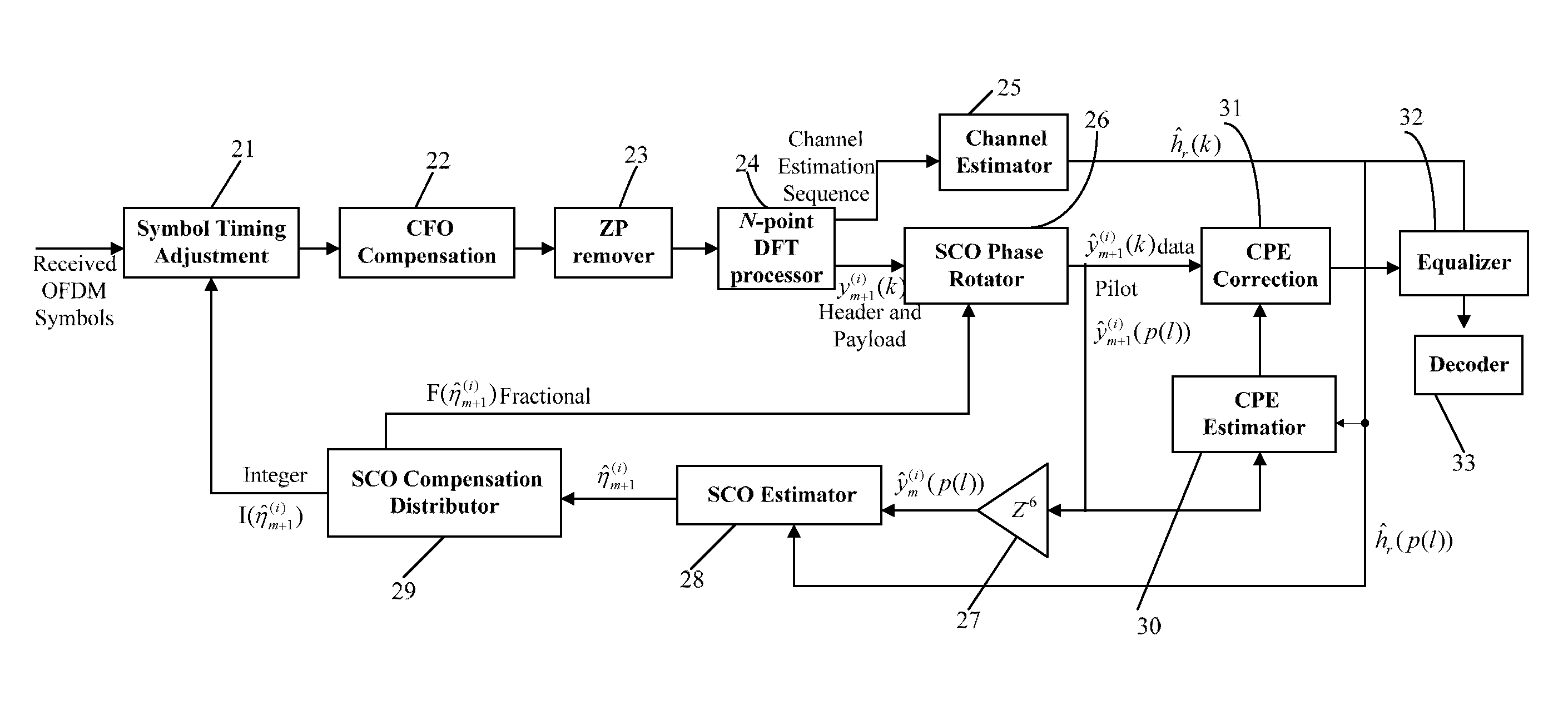
[0019]The preferred embodiments of the present invention will be described in detail by way of examples and with reference to the above-mentioned figures.

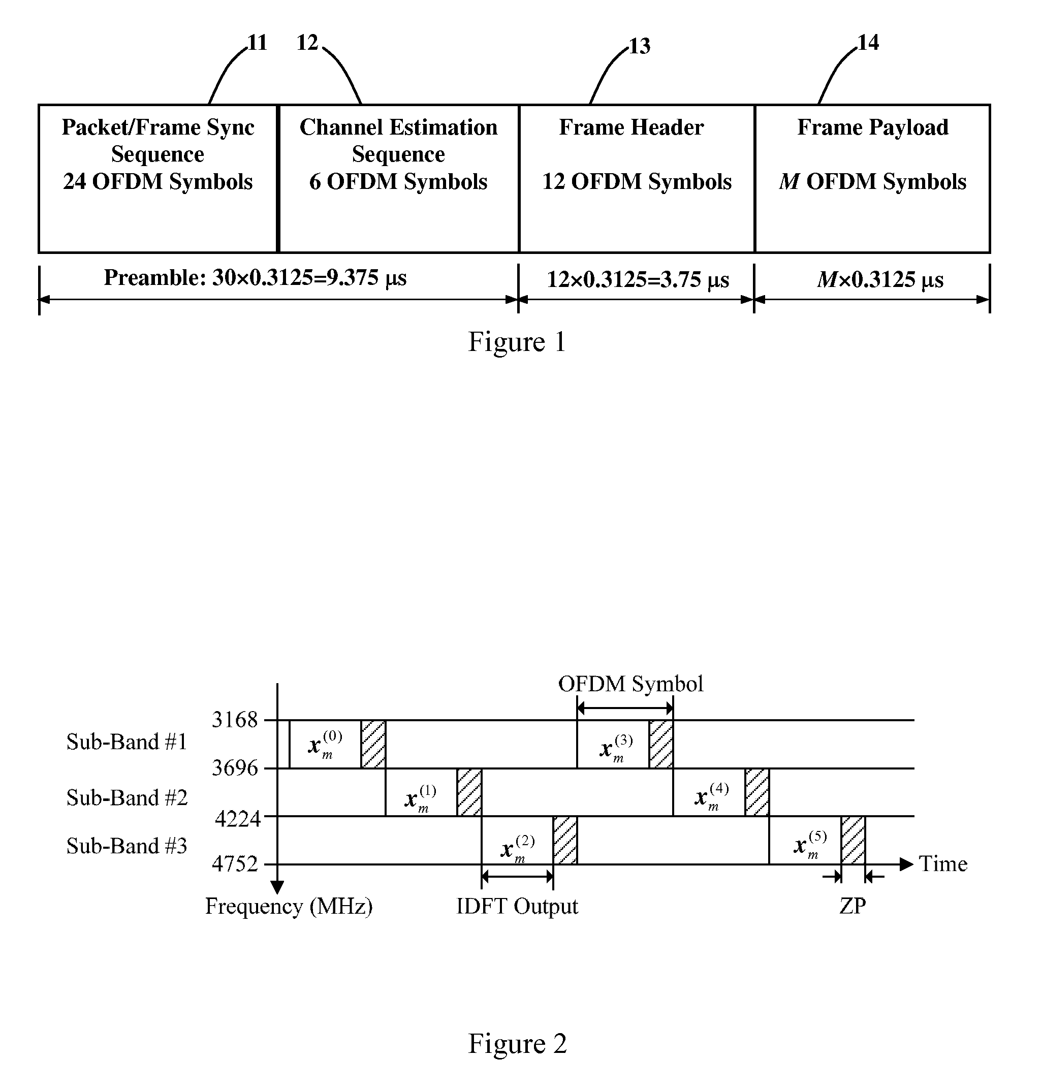
[0020]As shown in FIG. 1, each OFDM-UWB frame is composed of a frame preamble, a frame header 13 and a frame payload 14. The frame preamble consists of 30 OFDM symbols. The first 24 symbols of the frame preamble are referred to as packet / frame sync sequence 11 and the last K (K=6, in this embodiment) symbols of the frame preamble are referred to as channel estimation sequence 12 which is dedicated to channel estimation. The frame header 13 consists of 2K OFDM symbols which convey the information about the current frame's configuration. The frame payload 14 consists of M OFDM data symbols where M is an integer multiple of K, denoted by M=KP. The duration of each OFDM symbol is 0.3125 μs. Thus, the durations of the frame preamble, frame header 13 and frame payload 14 are respectively 9.375 μs, 3.75 μs and M×0.3125 μs. Denote by the ...


PUM


Abstract

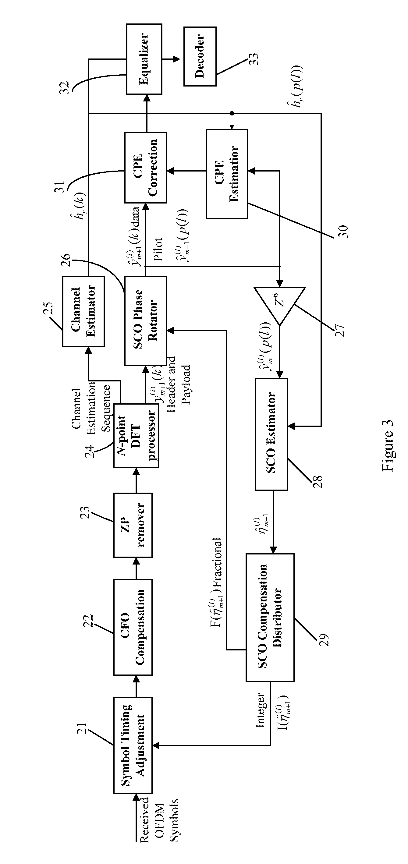
An apparatus for sampling clock recovery (SCO) and methods for estimating and compensating SCO are provided. The apparatus comprises a symbol timing adjustment module for shifting forward or backward symbol timing of the transmitted OFDM symbols; a discrete Fourier transform (DFT) processor for performing DFT to an output from the symbol timing adjustment module; a channel estimator for undertaking a channel frequency response estimation based on a channel estimation sequence; a SCO phase rotator for receiving and performing phase shift on the transmitted OFDM symbols of a frame header and a frame payload; an SCO estimation stage for undertaking an SCO estimation based on a pilot-subcarrier-related output of the SCO phase rotator and the CFR estimation; and an SCO compensation distributor for dividing the SCO estimation into integer and fractional portions and then distributing them into the symbol timing adjustment module and the SCO phase rotator, respectively.

Description

BACKGROUND OF THE INVENTION[0001]1. Field of the Invention[0002]The present invention relates to apparatus and methods for estimating and compensating sampling clock offset (SCO) for orthogonal frequency division multiplexing (OFDM) communications, and more particularly to the apparatus and the SCO estimation and compensation methods for multi-band OFDM-based ultra-wideband (UWB) systems.[0003]2. Description of Related Art[0004]Multi-band orthogonal frequency division multiplexing (OFDM) based ultra-wideband (UWB) communication has attracted considerable attention in the recent years, as described in the following two references: [1]“A. Batra, J. Balakrishnan, G R. Aiello, J. R. Foerster, and A. Dabak, “Design of a multiband OFDM system for realistic UWB channel environments,” IEEE Trans. Microwave Theory and Techniques, vol. 52, no. 9, pp. 2123-2138, September 2004.”; [2]“WiMedia MBOA, MultiBand OFDM Physical Layer Specification, ver. 1.1.5, Jul. 14, 2006.”. The large bandwidth occ...

Claims


Application Information

Patent Timeline
Patent Type & Authority Patents(United States)
IPC IPC(8): H04J11/00H04L27/00H04L25/00H04K1/10
CPCH04L27/2662H04L27/266H04L27/2675H04L27/2695
Inventor WANG, ZHONGJUNTOMISAWA, MASAYUKI
Owner WIPRO LTD
Learn More