Air duct and electronic equipment using the air duct

a technology of air ducts and air ducts, applied in the field of air ducts, can solve the problems of troublesome and laborious, troublesome and laborious, etc., and achieve the effects of easy replacement, high cooling effect, and easy disassembly and attachmen

Active Publication Date: 2005-02-17
FUJITSU LTD
View PDF14 Cites 31 Cited by
  • Summary
  • Abstract
  • Description
  • Claims
  • Application Information

AI Technical Summary

Benefits of technology

[0022] Further, electronic equipment of the invention is electronic equipment having one or not less than two various equipment in a housing and has the air duct 24 and a fan unit 26. The air duct 24 is detachably installed in the space 20 of the housing (exterior case 4, top plate 36) to form the ventilation path 28 through which the air is allowed to flow in the housing. The fan unit is installed in the air duct, and the cooling air is forced to flow through the ventilation path. With such a structure, the cooling air can be allowed to flow in the equipment through the air duct, and the air duct can be easily detached and attached. Further, it is possible to realize the electronic equipment having high cooling effect and the fan unit 26 installed in the air duct 24 can be easily replaced with another.
[0023] With such electronic equipment, a first window 34 through which the fan unit 26 is attached to, or detached from the air duct 24 is formed in the air duct, and a second window 40 corresponding to the first window 34 is formed in the housing (top plate 36) of the electronic equipment, wherein the first window and the second window can be opened or closed by a cover member 44 provided in the housing so that the first and second windows can be opened or closed by the cover member 44 and the fan unit can be easily attached to, or detached from the air duct through the first and second windows.

Problems solved by technology

Further, with such a chassis structure, it is not possible to design the air duct and the housing separately from each other so that they can not be assembled or disassembled.
Replacement of the ventilator requires an operation for removing the front cover plate and the front face sealed plate, then removing a metallic enclosure enclosing the chassis, and separating the upper portion from the lower portion of the chassis, which is very troublesome and takes labor.
This technique is however discloses that the chassis per se is merely rendered to be air duct, and an air duct is not formed relative to a specific component, and the replacement of a fan requires the operation for removing the top plate from the chassis and removing the sealed case from the chassis, which is very troublesome and takes labor.

Method used


Image

  • Air duct and electronic equipment using the air duct
  • Air duct and electronic equipment using the air duct
  • Air duct and electronic equipment using the air duct

Examples


first embodiment

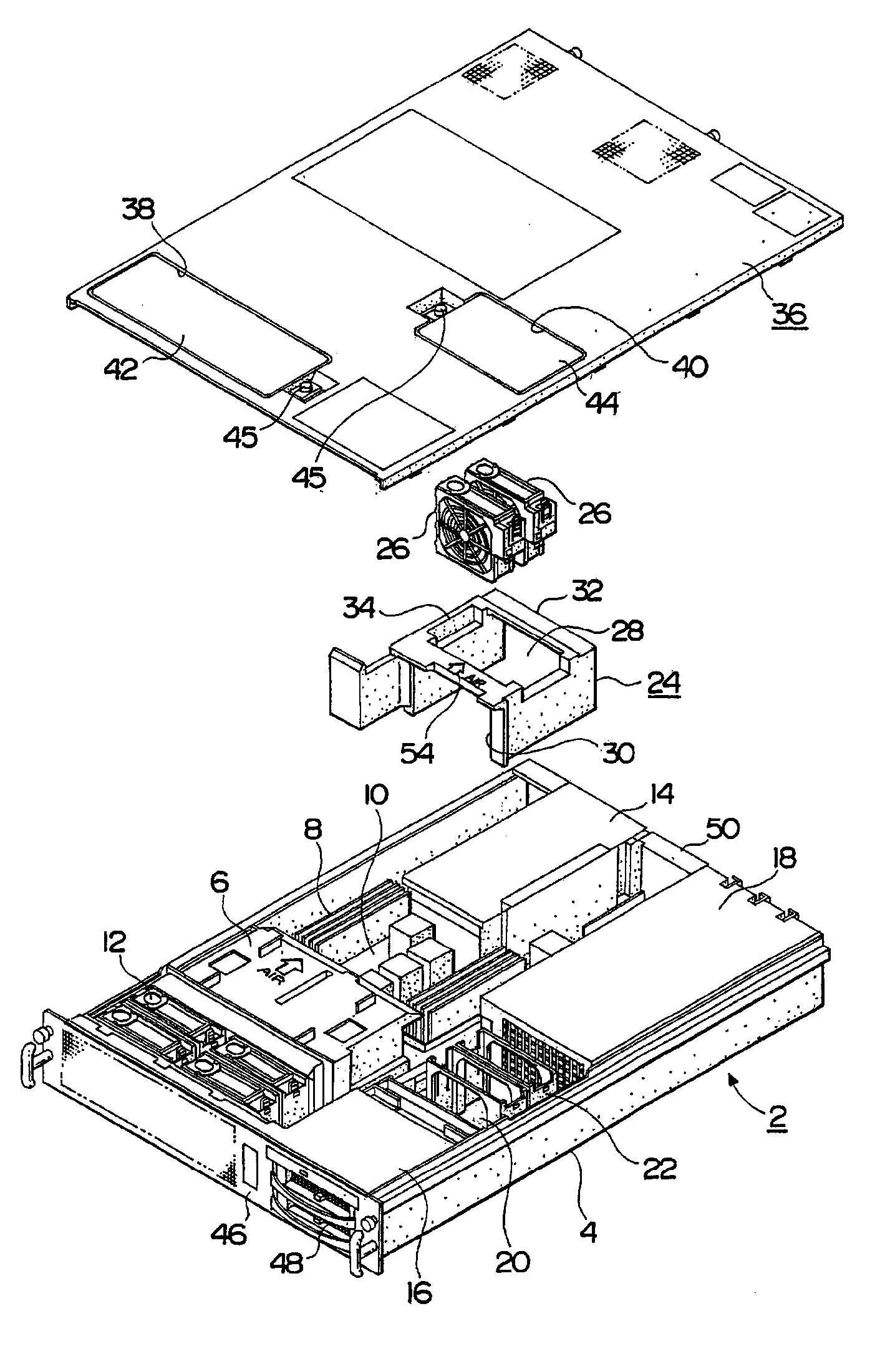
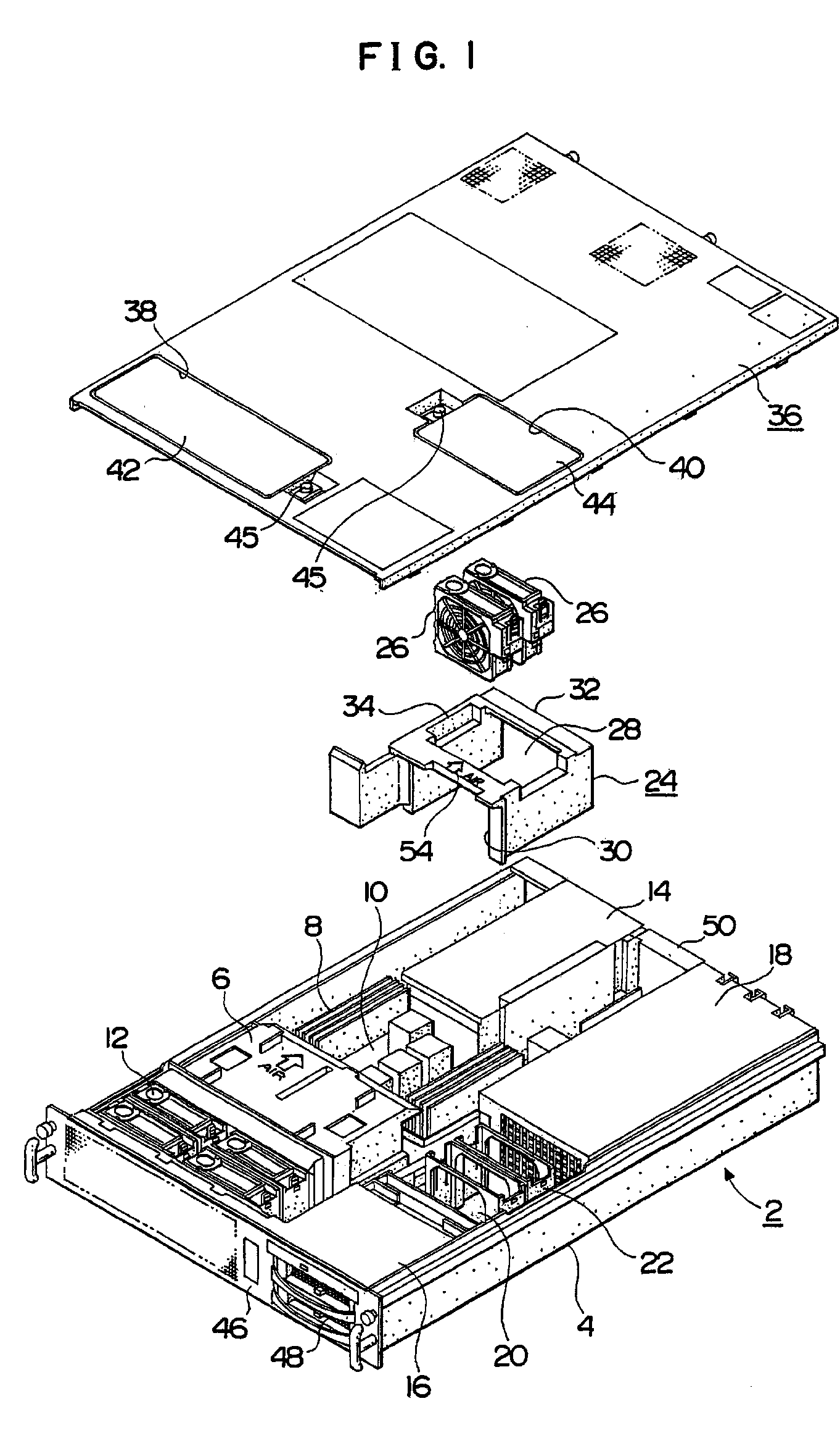
[0026]Fig. 1 is a perspective view showing an air duct and electronic equipment according to the invention;

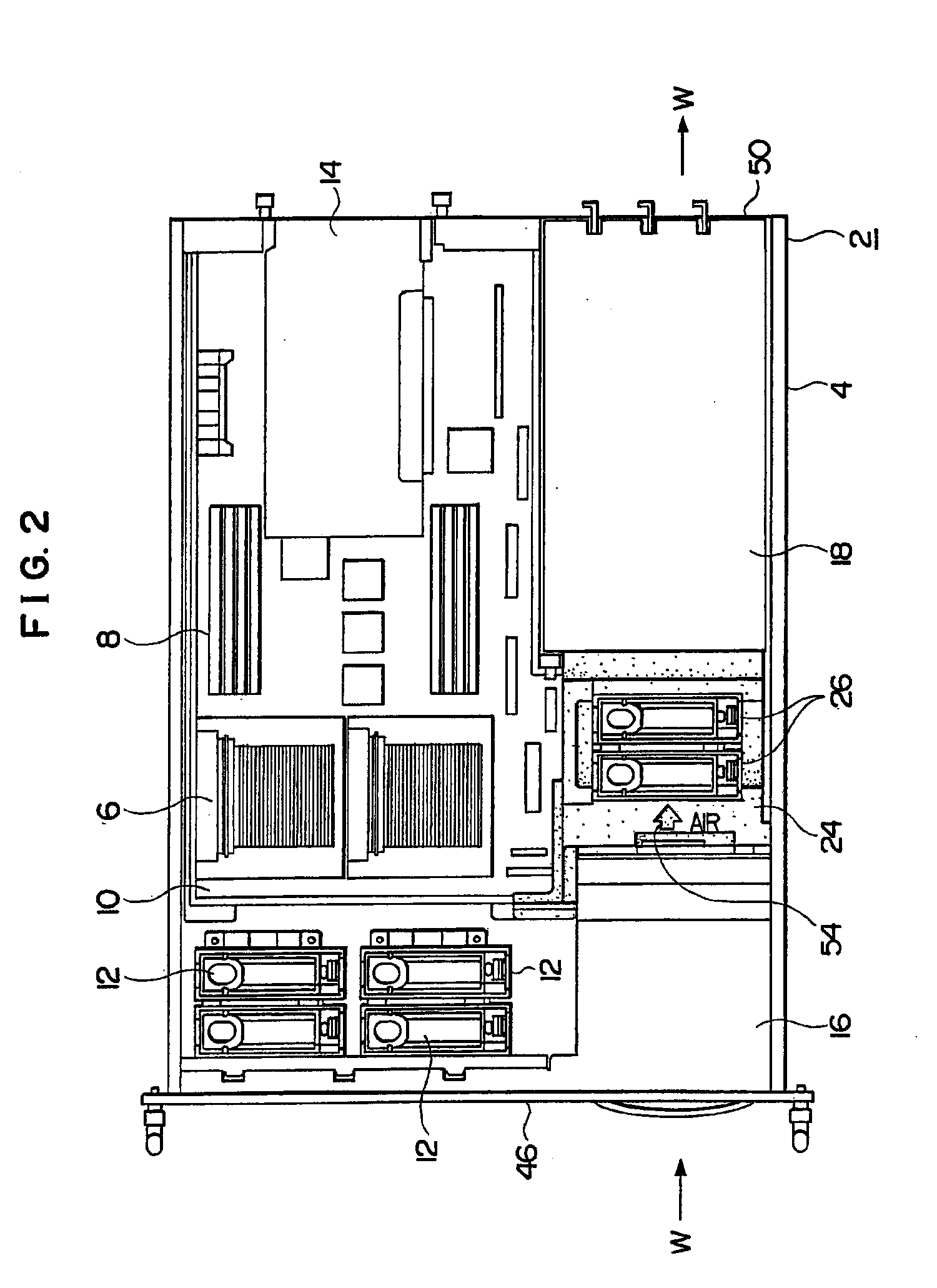
[0027]Fig. 2 is a plan view showing the electronic equipment in which the air duct is installed;

[0028]Fig. 3 is a plan view showing a front face panel of the electronic equipment;

[0029]Fig. 4 is a plan view showing a rear face panel of the electronic equipment;

[0030]Fig. 5 is a perspective view showing the air duct as viewed from an intake part side;

[0031]Fig. 6 is a perspective view showing the air duct as viewed from an exhaust part side;

[0032]Fig. 7 is a plan view showing the electronic equipment before the air duct is installed in the electronic equipment;

[0033]Fig. 8 is an enlarged view showing a space in which the air duct is installed;

[0034]Fig. 9 is a plan view showing an air duct;

[0035]Fig. 10 is a front view showing an air duct;

[0036]Fig. 11 is a rear view showing an air duct;

[0037]Fig. 12 is a side view showing an air duct;

[0038]Fig. 13 is a perspective view showing ...

second embodiment

[0046]Fig. 21 is a view showing an air duct according to the invention.

DETAILED DESCRIPTION OF THE PREFERRED EMBODIMENTS

[0047] First Embodiment:

[0048] A first embodiment of the invention is now described. Figs. 1 to 4 show an air duct and electronic equipment according to the first embodiment of the invention, wherein Fig. 1 shows the electronic equipment from which a top plate, a fan unit and the air duct are separated, Fig. 2 shows an interior of the electronic equipment in which the air duct is installed, Fig. 3 shows a front face panel of the electronic equipment, and Fig. 4 shows a rear face panel of the electronic equipment.

[0049] An electronic equipment 2 has an exterior case 4 serving as a housing, and there are provided in the exterior case 4 a plurality of circuit elements constituting the electronic equipment 2, components of a circuit board such as a circuit board 10 on which a plurality of CPUs (Central Processing Unit) 6, a memory 8 and so forth are mounted, a fan uni...


PUM


Abstract

Abstract of the Disclosure
The invention relates to an air duct for allowing cooling air to flow toward an electronic equipment, and provides the air duct for allowing cooling air to flow installed in a space in the equipment and also provides an electronic equipment using the same air duct. The air duct is structured to be formed of an elastic material, and has a duct body, a ventilation path, an intake part, and an exhaust part. The duct body is detachably installed in a space of an interior of the equipment, and the ventilation path through which air passes is formed in the duct body, and an intake part for taking air in the ventilation path and an exhaust part for exhausting air through the ventilation path are formed respectively in the duct body.

Description

Detailed Description of the InventionBACKGROUND OF THE INVENTION[0001] 1. Field of the Invention:[0002] The invention relates to an air duct for forming an air path in a space inside electronic equipment, particularly, an air duct having a structure which is easily disassembled and assembled and electronic equipment using the air duct.[0003] 2. Description of the Related Art:[0004] Heat radiation and cooling in electronic equipment are conventionally indispensable to prevent the deterioration and keep stability and reliability of the operation of the electronic equipment. A cooling fan has been generally used for cooling the electronic equipment, and heating portion such as heating components and the like is cooled by air which is taken in the electronic equipment. For example, if a cooling fan is installed at the rear panel side to exhaust air, cooling air is sucked from the front panel side and so forth into the electronic equipment and it flows in the electronic equipment so ...

Claims


Application Information

Patent Timeline
Patent Type & Authority Applications(United States)
IPC IPC(8): H05K9/00F04D29/60F04D29/70F25D1/00H05K7/20
CPCF04D19/007F04D29/522F04D29/668F04D29/663F04D29/646F04D29/601F04D29/703H05K7/20172
Inventor KOSUGI, NAOFUMI
Owner FUJITSU LTD
Why Eureka
Try Eureka