
Methods and apparatus for preventing migration of sutures through transosseous tunnels

Inactive Publication Date: 2005-02-17
DEPUY MITEK INC
View PDF97 Cites 27 Cited by
  • Summary
  • Abstract
  • Description
  • Claims
  • Application Information

AI Technical Summary

Benefits of technology

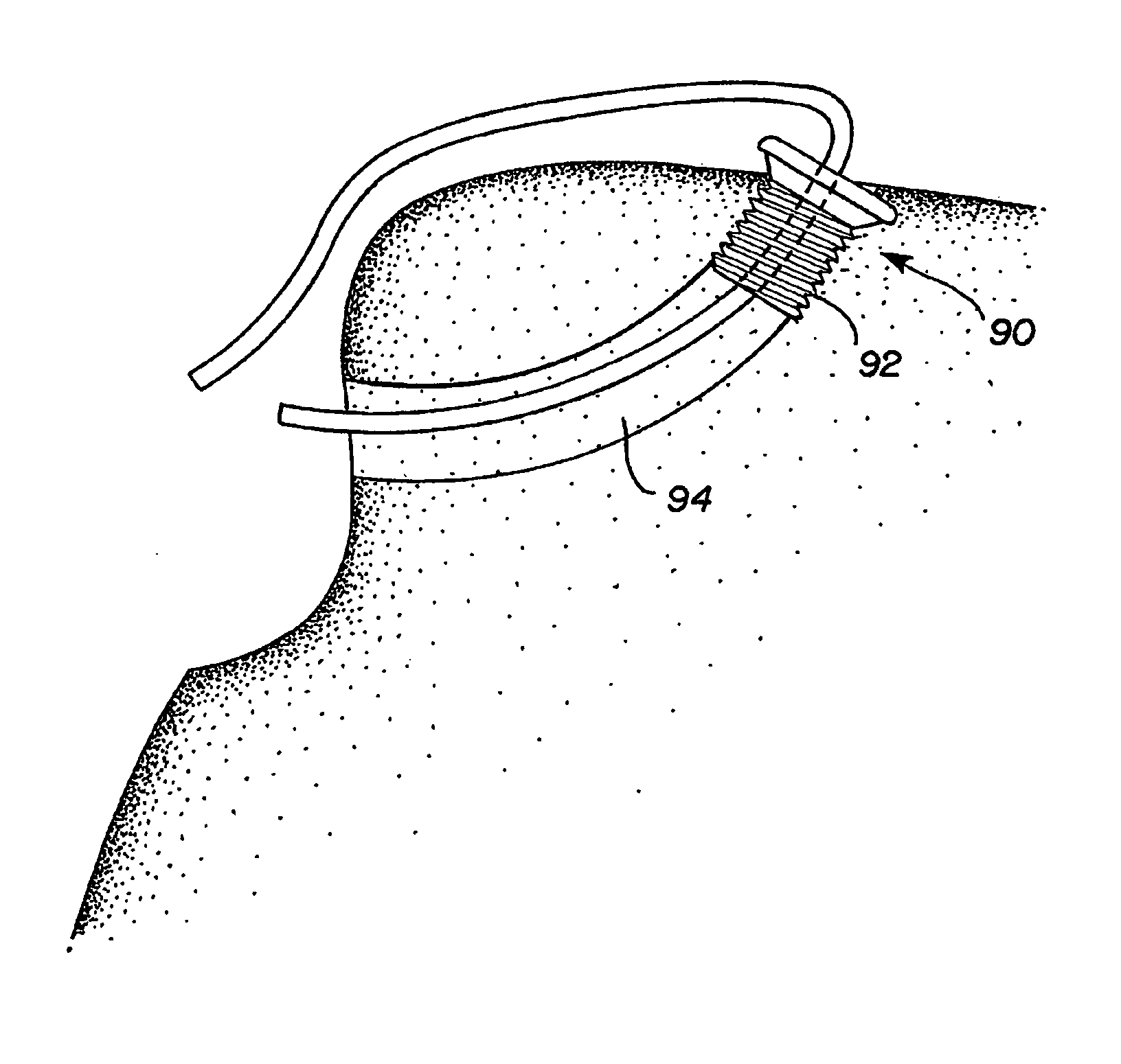
[0013] In another aspect, the invention provides an apparatus for use in rotator cuff repair for reinforcing a transosseous tunnel to prevent migration of a suture through bone at the end of the tunnel. The apparatus comprises an eyelet arranged for placement within the end of the tunnel, or within an expanded hole formed at the end of the tunnel. The eyelet has a channel therethrough for passage of the suture and can include a flanged head to prevent the eyelet from being forced too far into the tunnel.

Problems solved by technology

Athletes, for example, often suffer “rotator cufftears, in which the supraspinatus tendon separates from the humerus, causing pain and loss of ability to elevate and externally rotate the arm.
Drawbacks of plate-like augmentation of the greater tuberosity are the difficulties in positioning and affixing the plates.

Method used


Image

  • Methods and apparatus for preventing migration of sutures through transosseous tunnels
  • Methods and apparatus for preventing migration of sutures through transosseous tunnels
  • Methods and apparatus for preventing migration of sutures through transosseous tunnels

Examples


Embodiment Construction

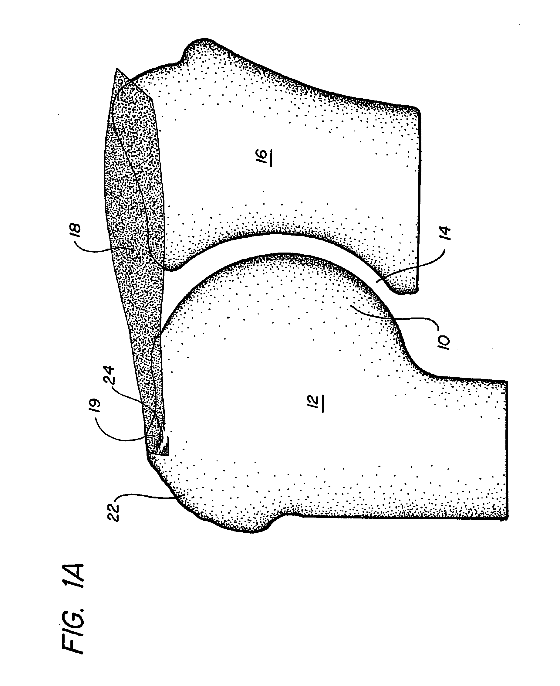
[0027]FIG. 1A depicts a partially torn rotator cuff. In the illustration, the globular head 10 of humerus 12 rests in the glenoid cavity 14 formed by the scapula 16. The supraspinatus muscle 18 traverses the scapular spine (not shown) and converges into a tendon 19 (undifferentiated in the illustration), then end of which is normally fully inserted into a facet of the greater tuberosity 22. A partial tear rotator cuff tear results when a portion 24 of the tendon 19 detaches from the greater tuberosity 22, as shown in the illustration.

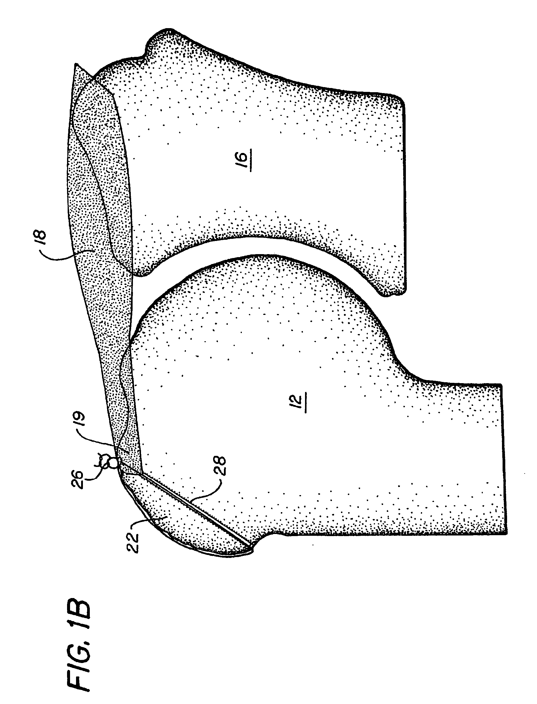
[0028]FIG. 1B illustrates the rotator cuff of FIG. 1A repaired in accord with the prior art suturing technique, in which the tendon 19 is resecured to the humerus by a suture 26 passed through a transosseous tunnel 28 bored obliquely through the greater tuberosity 22. A further understanding of the prior art suturing technique may be attained by reference to Gerber, et al, “Mechanical Strength of Repairs of the Rotator Cuff,” Journal of Bone and Joint ...


PUM


Abstract

An improved method for attaching soft tissue to bone by passing a suture through an opening in the bone, e.g., a transosseous tunnel, and affixing the soft tissue with the suture. The improvement, for preventing the suture from migrating through the bone at the end of the opening, includes placing a eyelet into an end of the bone opening and passing the suture through the eyelet, as well as through the opening in the bone, in order to affix the soft tissue to the bone with the suture.

Description

CROSS-REFERENCE TO RELATED APPLICATIONS [0001] This application is a continuation of U.S. application Ser. No. 09 / 981,623, filed on Oct. 16, 2001, which is a continuation of U.S. application Ser. No. 09 / 324,022, filed on Jan. 19, 1999, which is a continuation-in-part of U.S. application Ser. No. 08 / 689,443, filed on Aug. 9, 1996, which is a continuation-in-part of U.S. application Ser. No. 08 / 163,130, filed on Dec. 6, 1993, which is a continuation-in-part of U.S. application Ser. No. 07 / 765,445, filed on Sep. 25, 1991, which is a continuation-in-part of U.S. application Ser. No. 07 / 588,055, filed on Sep. 24, 1990. The entire contents of these applications are incorporated herein by reference.BACKGROUND OF THE INVENTION [0002] This invention pertains to surgical systems and, more particularly, methods and apparatus for attaching tissue to bone. The invention has application in, for example, rotator cuff repair. [0003] It is not uncommon for tendons and other soft tissues to tear or t...

Claims


Application Information

Patent Timeline
IPC IPC(8): A01B1/22A61B17/04A61B17/56A61B17/32A61B17/68A61B17/82A61B19/00A61F2/08A61F2/28B05C17/10
CPCA01B1/222Y10S623/902A61B17/0467A61B17/32053A61B17/686A61B17/82A61B2017/0403A61B2017/0406A61B2017/0409A61B2017/0414A61B2017/0424A61B2017/0425A61B2017/044A61B2017/0445A61B2017/045A61B2017/0458A61B2017/0464A61B2019/307A61F2/0805A61F2/0811A61F2002/0835A61F2002/0841A61F2002/0864A61F2002/0882A61B17/0401A61B2090/037
Inventor MCDEVITT, DENNISNICHOLSON, JAMES
Owner DEPUY MITEK INC
Learn More