
Evaluating ventricular synchrony based on phase angle between sensor signals

a phase angle and sensor technology, applied in electrotherapy, heart stimulators, therapy, etc., can solve problems such as heart failure, ventricular dysynchrony, and render a v-v interval selected by a physician on the basis of an acute echocardiograph inappropriate, so as to reduce or eliminate ventricular dysynchrony

Inactive Publication Date: 2005-02-17
MEDTRONIC INC
View PDF11 Cites 92 Cited by
  • Summary
  • Abstract
  • Description
  • Claims
  • Application Information

AI Technical Summary

Benefits of technology

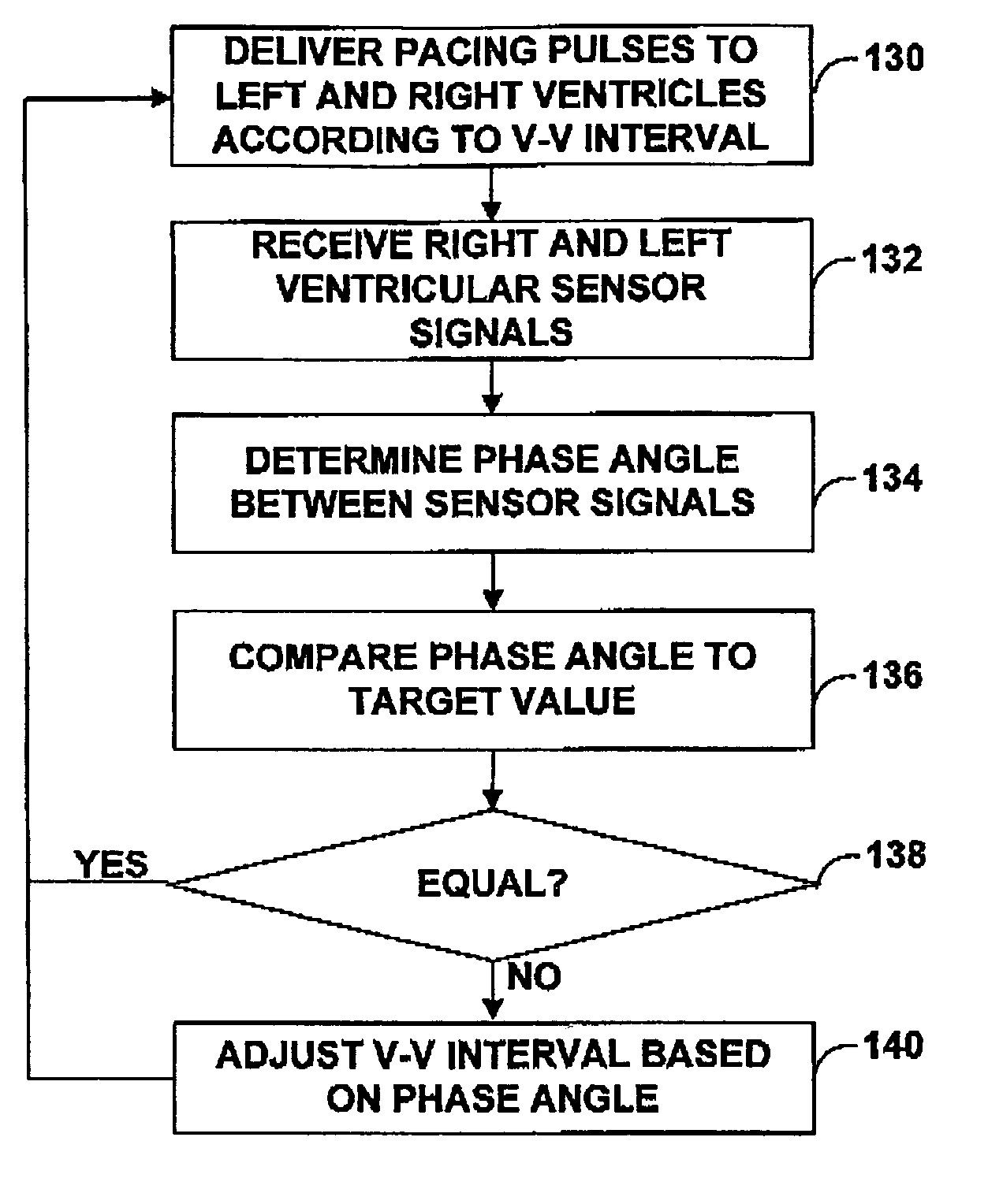
[0005] In general, the invention is directed to techniques for evaluating ventricular synchrony based on the phase angle between sensor signals. In exemplary embodiments, a medical device according to the invention, such as an implantable medical device (IMD), delivers cardiac resynchronization therapy (CRT) pacing, and adjusts one or more timing intervals for the CRT pacing, such as a V-V interval, based on the phase angle. Such a medical device can dynamically adjust the timing interval(s) to reduce, or possibly eliminate, ventricular dysynchrony.

Problems solved by technology

Ventricular dysynchrony is caused by conduction delays within the ventricles.
As a result of ventricular dysynchrony, the heart pumps blood less efficiently resulting in symptoms of heart failure.
Over time, the condition or disease of a patient can change, rendering a V-V interval selected by a physician on the basis of an acute echocardiograph inappropriate.
These techniques, however, are only able to indirectly evaluate ventricular synchrony.
Further, the physiological parameters monitored can vary over time due to factors other than changes in the dysynchrony of the ventricles, potentially leading to selection of an inappropriate V-V interval.

Method used


Image

  • Evaluating ventricular synchrony based on phase angle between sensor signals
  • Evaluating ventricular synchrony based on phase angle between sensor signals
  • Evaluating ventricular synchrony based on phase angle between sensor signals

Examples


Embodiment Construction

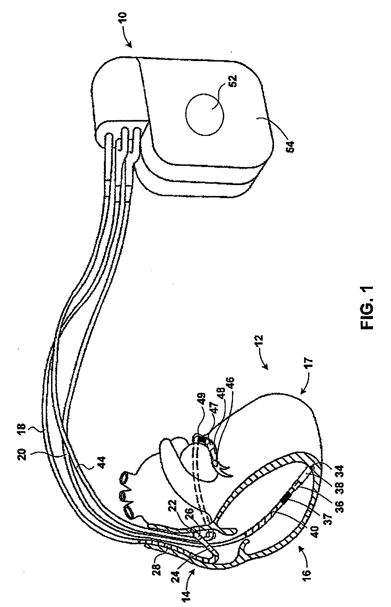
[0015]FIG. 1 depicts an exemplary implantable medical device (IMD) 10 that evaluates ventricular synchrony according to the invention. In the illustrated example, IMD 10 takes the form of a multi-chamber implantable cardioverter-defibrillator (ICD). IMD 10 is implanted within a patient (not shown), and includes leads 18, 20 and 24 that extend into a heart 12 of the patient.

[0016] Right trial (RA) lead 18 extends into the right atrium 14 of heart 12. Right ventricular (RV) lead 20 extends through the right atrium 14, and into the right ventricle 16 of heart 12. Left ventricular (LV) coronary sinus lead 44 extends through the right atrium 14, and into the coronary sinus of heart 12 to a point adjacent to the free wall of left ventricle 17 of heart 12.

[0017] Leads 18, 20 and 44 include electrodes for sensing electrical activity attendant to the depolarization and repolarization of heart 12, and for delivering pacing pulses to heart 12. In the illustrated embodiment, bipolar electrode...


PUM


Abstract

An implantable medical device evaluates ventricular synchrony by determining a phase angle between at least two sensor signals that reflect mechanical contraction of the ventricles. In exemplary embodiments, two intracardiac impedance signals associated with the right and left ventricles, respectively, with two points within either of the left and right ventricles, or with both the left and right ventricles relative to a reference point, are processed. In such embodiments, fundamental frequency phases of each of the impedance signals may be compared to determine the phase angle between the signals. In some embodiments, the signals are used to dynamically adjust one or more timing intervals, such as a V-V timing interval, for delivery of cardiac resynchronization therapy (CRT) pacing. In such embodiments, the one or more timing intervals are periodically adjusted to reduce or possibly eliminate ventricular dysynchrony as indicated by the phase angle between the sensor signals.

Description

TECHNICAL FIELD [0001] The invention relates to implantable medical devices, and more particularly, to implantable medical devices that provide cardiac pacing. BACKGROUND OF THE INVENTION [0002] Ventricular dysynchrony is characterized by non-simultaneous ventricular contractions. In particular, movement of an apical region of the heart is out of synch with movement of the left-ventricular free wall of the heart. Ventricular dysynchrony is caused by conduction delays within the ventricles. The conduction delays are caused by, for example, bundle branch blocks or infracted tissue within the myocardium. Typically, ventricular dysynchrony is assessed in a clinical setting via echocardiography. [0003] As a result of ventricular dysynchrony, the heart pumps blood less efficiently resulting in symptoms of heart failure. Consequently, some patients diagnosed with ventricular dysynchrony receive cardiac resynchronization therapy (CRT) pacing. CRT pacing therapies typically involve delivery ...

Claims


Application Information

Patent Timeline
Patent Type & Authority Applications(United States)
IPC IPC(8): A61N1/362A61N1/368
CPCA61N1/368A61N1/3627
Inventor CHINCHOY, EDWARDDENO, D. CURTISCHO, YONG K.
Owner MEDTRONIC INC
Learn More