

Foam encased innerspring with internal foam components (triple case)
- Summary
- Abstract
- Description
- Claims
- Application Information
AI Technical Summary
Benefits of technology
Problems solved by technology
Method used
Image

Examples
Embodiment Construction
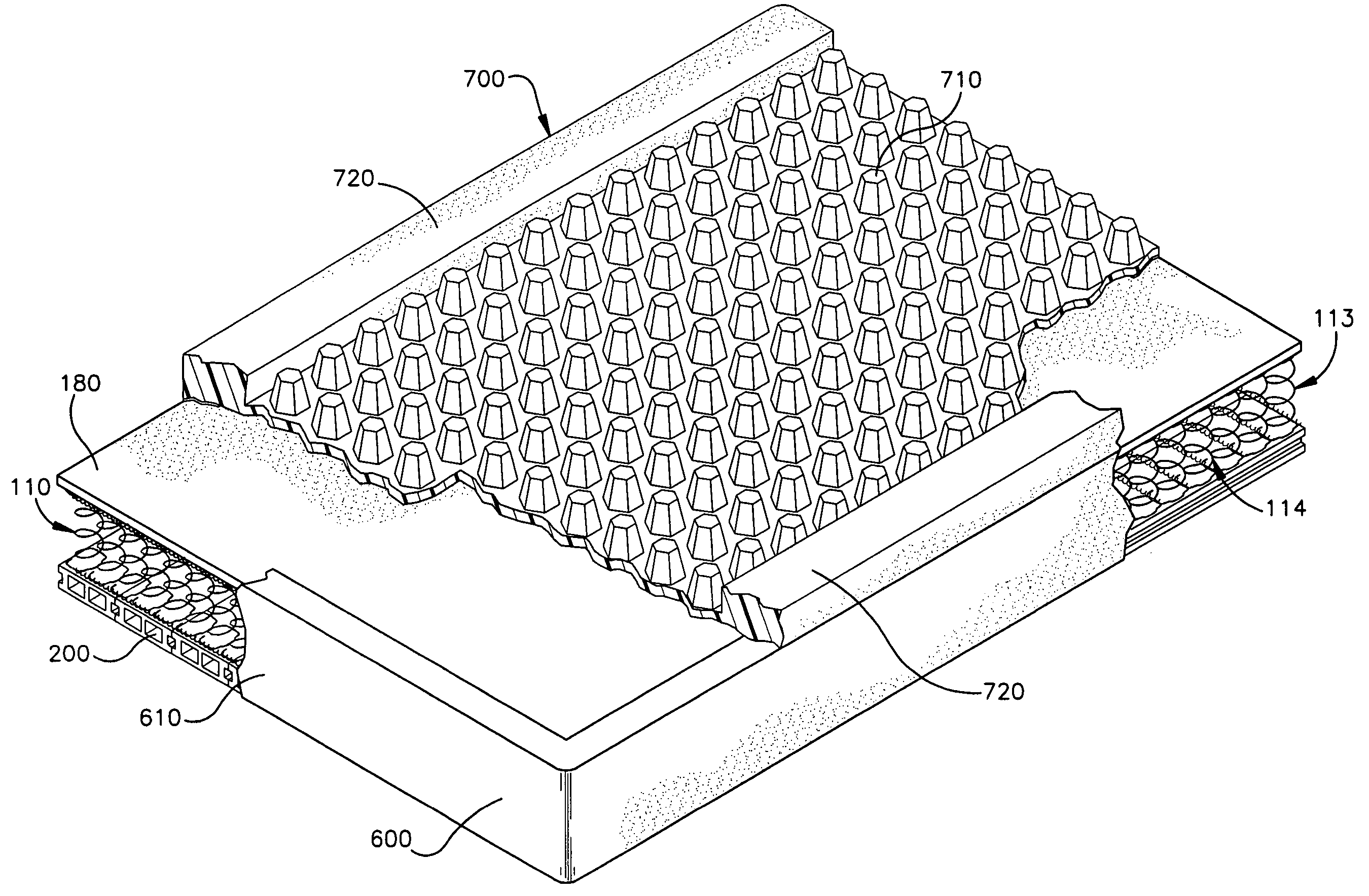
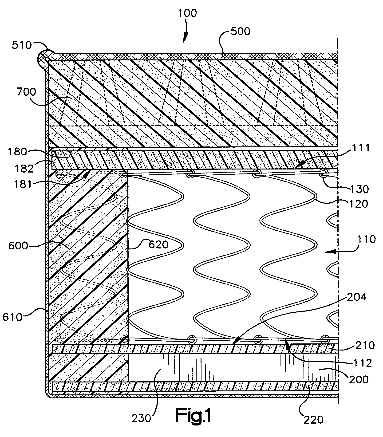
[0018] With reference to FIG. 1, there is illustrated a structurally integrated foam encased support device, referenced generally as 100, which in this particular embodiment of the invention is in the form of a one-sided mattress, as further described. The device 100 includes an innerspring and internal and external foam components. The innerspring 110 (also sometimes referred to herein as an “innerspring assembly”) is made up of a plurality of wire form coils 120 which are interconnected or laced together by helical wires 130 as known in the art, in an array to form an assembly which has a first support side generally defined by aligned first ends of the coils or spring elements, and a second support side generally defined by the aligned second ends of the coils or spring elements, the first and second support sides being parallel, and a perimeter about the first and second support sides defined by perimeter coils at the edges of the array, defining a generally rectangular shape to...
PUM
| Property | Measurement | Unit |
|---|---|---|
| Density | aaaaa | aaaaa |
| Flexibility | aaaaa | aaaaa |
| Area | aaaaa | aaaaa |
Abstract
Description
Claims
Application Information