Cylinder head structure of engine

a technology of cylinder head and engine, which is applied in the direction of engine cooling apparatus, cylinders, liquid cooling, etc., can solve the problems of reducing engine output, reducing the density of gas supplied into cylinders, and inability to efficiently cool intake ports and exhaust ports. to achieve the effect of efficient cooling intake ports

Active Publication Date: 2005-02-24
MITSUBISHI MOTORS CORP
View PDF12 Cites 8 Cited by
  • Summary
  • Abstract
  • Description
  • Claims
  • Application Information

AI Technical Summary

Benefits of technology

[0009] The present invention provides a cylinder head structure of

Problems solved by technology

In the cylinder head, however, the temperature of the spark plug mounting parts and the temperature of the exhaust ports are high, and hence the cooling water heats up while flowing along the spark plug mounting parts

Method used


Image

  • Cylinder head structure of engine
  • Cylinder head structure of engine
  • Cylinder head structure of engine

Examples


Embodiment Construction

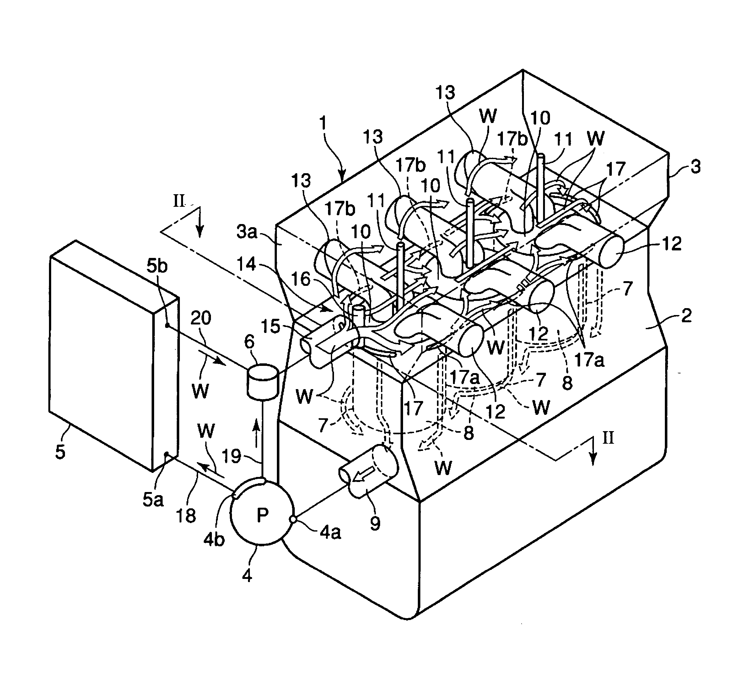
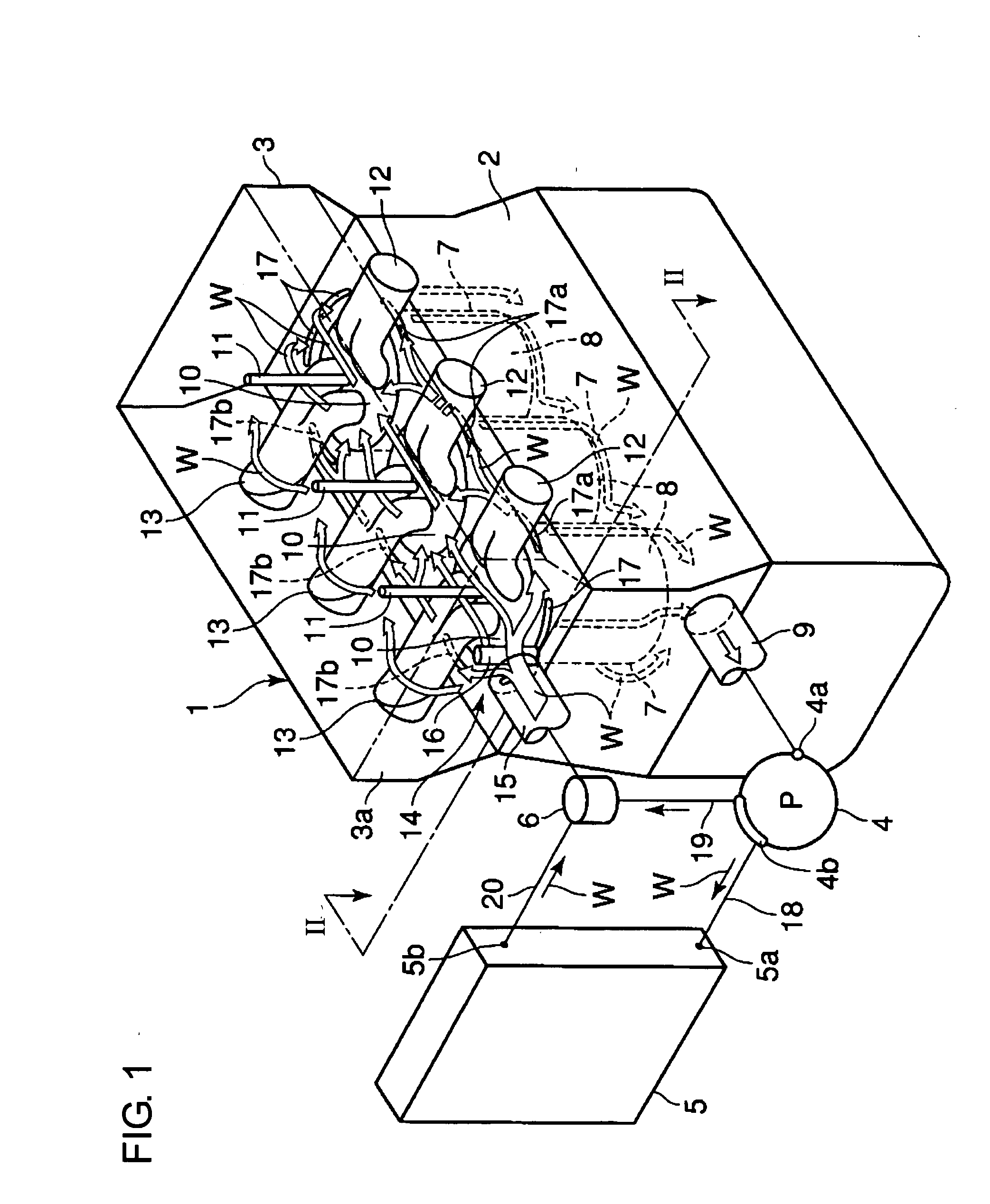
[0015] A description will now be given of an engine 1 according to an embodiment of the present invention with reference to FIGS. 1 to 3. The engine 1 in FIG. 1 is comprised of a cylinder block 2, a cylinder head 3, a water pump 4, a radiator 5, and a thermostat 6. In the cylinder block 2, water jackets 8, as block cooling passages, are disposed along the outer circumferences of cylindrical surfaces of cylinders 7. In FIG. 1, arrows indicate flow of cooling water. The cylinder block 2 is provided with an outlet 9 located away from the cylinder head 3 and in communication with the water jackets 8.

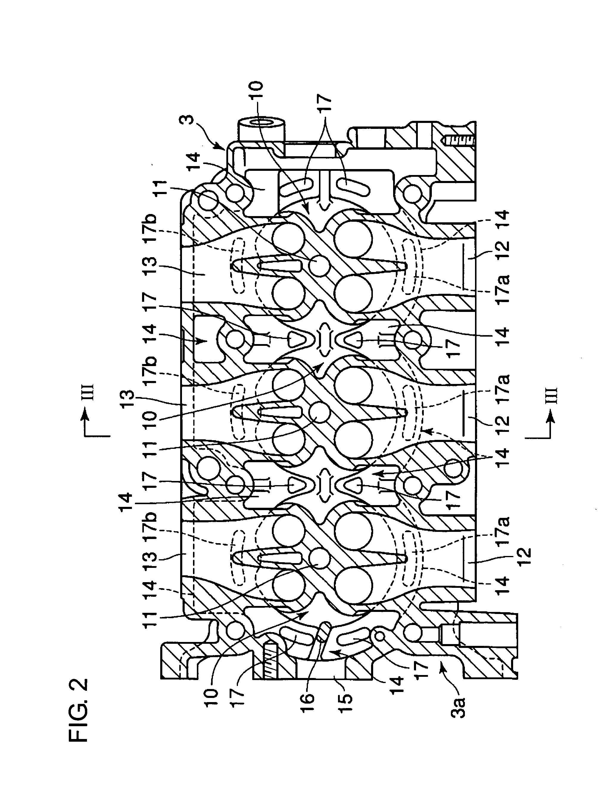
[0016] The cylinder head 3 is provided with combustion chambers 10, spark plug mounting parts 1, intake ports 12, exhaust ports 13, and head cooling passages 14. The spark plug mounting parts 1 are located such that spark plugs are closer to the exhaust ports 13 relative to the axes of the cylinders 7. The intake ports 12 are opened in such a direction as to cross the central axes of the cy...


PUM


Abstract

Head cooling passages are formed around intake ports and exhaust ports provided in a cylinder head, and a flow control member which controls the volume of cooling medium flowing toward the intake ports to be larger than the volume of cooling medium flowing toward the exhaust ports is provided in the vicinity of a supply port via which cooing medium is supplied.

Description

CROSS-REFERENCE TO RELATED APPLICATION [0001] This application incorporates by reference the subject matter of Application No. 2003-197843 filed in Japan on Jul. 16, 2003, on which a priority claim is based under 35 U.S.C. § 119(a).BACKGROUND OF THE INVENTION [0002] 1. Field of the Invention [0003] The present invention relates to a cylinder head structure of an engine in which a cooling medium is supplied to a cylinder head. [0004] 2. Description of the Related Art [0005] An engine of the type that cooling water discharged from a cooling pump is supplied to a cylinder head before it is supplied to a cylinder block to efficiently cool the cylinder head has been disclosed in Japanese Utility Model Examined Publication No. 4-44816 (refer to the fourth line in the fifth row in the right column of the third page to the third line in the ninth row of the right column of the fifth page, and FIGS. 1 to 6). In such an engine, cooling water is supplied from a cooling water inlet provided at ...

Claims


Application Information

Patent Timeline
IPC IPC(8): F01P3/02F02F1/10F02F1/36F02F1/38F02F1/40
CPCF01P3/02F01P2003/021F02F1/40F01P2003/028F01P2003/024
Inventor YAMAMOTO, AKIMASA
Owner MITSUBISHI MOTORS CORP
Why Eureka
Try Eureka