Apparatus for trapping floating and non-floating particulate matter

a technology for floating and non-floating particulate matter, applied in separation processes, liquid displacement, filtration separation, etc., can solve the problems of insufficient to allow a worker to enter the device, reduce or eliminate the effectiveness of the stormwater treatment device, etc., and achieve cost-effective and efficient effects

Inactive Publication Date: 2005-02-24
BRYANT GRAHAM
View PDF1 Cites 14 Cited by
  • Summary
  • Abstract
  • Description
  • Claims
  • Application Information

AI Technical Summary

Benefits of technology

[0013] It is an object of the present invention to provide a stormwater separation tank that can remove floating and non-floating particulate matter from storm water in a cost effective and efficient manner. In the invention, the separation tank may include an outer chamber and an inner chamber positioned within the outer chamber. Preferably, the inner chamber is a generally cylindrical construction comprised of a cylindrical wall having an interior cylindrical surface. An inlet is provided in the outer chamber to receive the flow of water to be treated and an outlet is provided in the outer chamber to discharge that water after it has been treated in the stormwater separation tank.

Problems solved by technology

One of the difficulties in the removal of such materials from stormwater is the need to take into account different flows of that water.
One of the problems in dealing with both high and low flows is that the debris and other material may be effectively removed and settled in the particular stormwater equipment at the low flow conditions, however, when the flow is then elevated to a high flow condition, that high flow effectively scours out the previously settled material and then is carried downstream, thereby reducing or eliminating the effectiveness of the stormwater treatment device.
As a further problem in dealing with the differing flows, the high flow streams of water carry additional trash and larger solids that are only picked up and carried along by the higher flows and therefore there is a need to be able to capture that trash and larger solids with the stormwater treatment device.
In the stormwater treatment device of that patent application, however, the incoming stream of water to be treated enters an inner chamber in a direction that is perpendicular to the wall of the inner chamber and the water thereby directly hits the wall of the inner chamber where turbulence is created during both high and low flow conditions.
As a further difficulty with the stormwater treatment device of the aforesaid patent application, the device requires the installation of two sets of weirs, that is, two high and two low weirs in carrying out the treatment of the water flowing therethrough and those weirs must be installed in the field during the installation of the treatment device at the intended site.
That use of two sets of weirs, however, along with the centralized location of the inner chamber, offers limited space within the overall water separation device by the use of the multiple weirs and is insufficient to allow a worker to enter the device to carry out that installation.

Method used


Image

  • Apparatus for trapping floating and non-floating particulate matter
  • Apparatus for trapping floating and non-floating particulate matter
  • Apparatus for trapping floating and non-floating particulate matter

Examples


Embodiment Construction

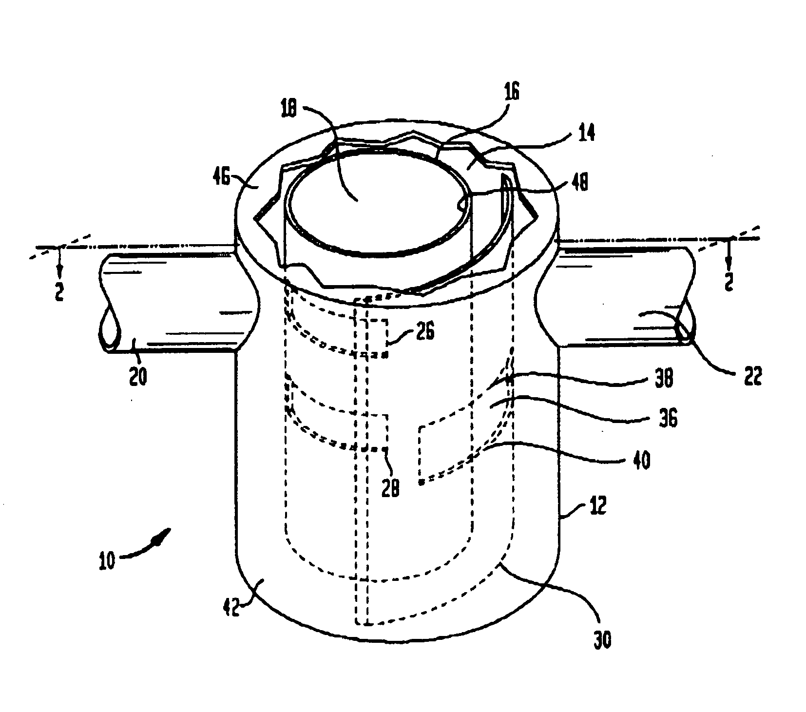
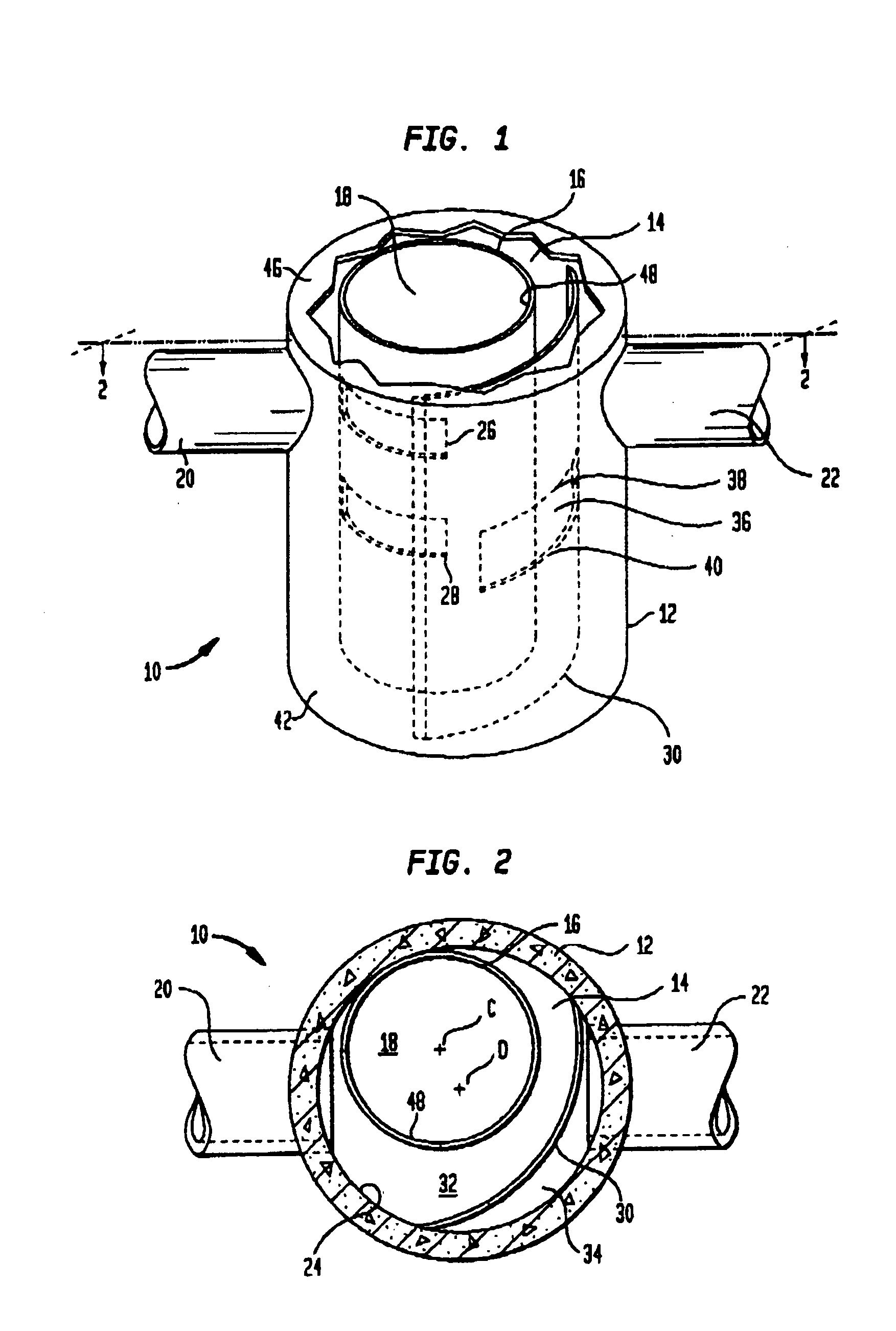
[0025] Referring now to FIGS. 1 and 2, there is shown a separation tank 10 constructed in accordance with the present invention. The separation tank 10 may be constructed of an outer chamber wall 12 and forms an outer chamber 14 and, likewise, there is an inner chamber wall 16 forming an inner chamber 18. In both cases, the outer chamber and inner chamber walls 12, 16 may be cylindrical walls and the outer chamber wall 12 and inner chamber wall 16 can be constructed of a pre-cast concrete, fiberglass, plastic steel or similar types of material, it not being essential to the invention as to the particular material.

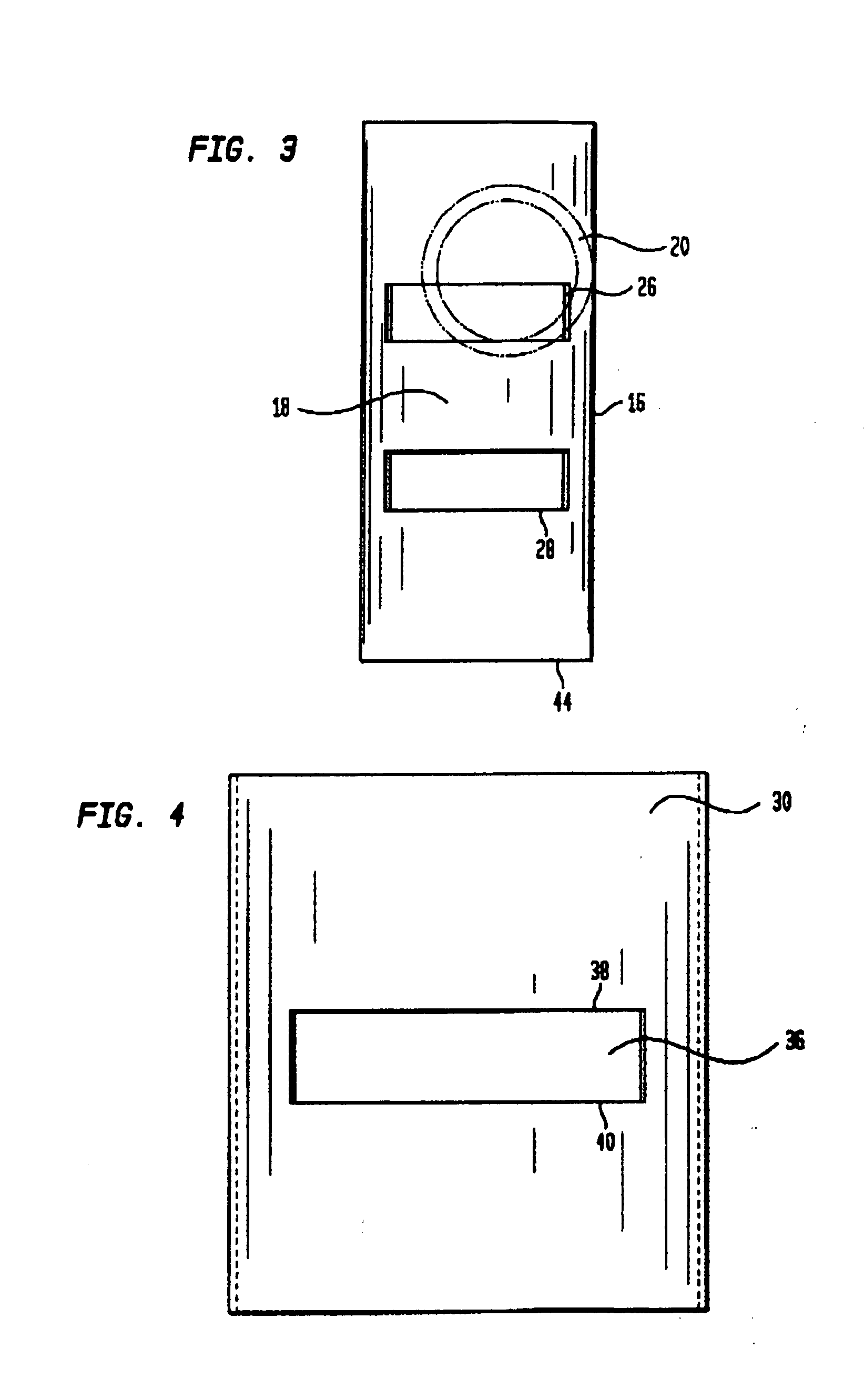
[0026] An inlet 20 is formed in the outer chamber wall 12 that is adapted to receive the flowing water to be treated. As will be seen the vertical location of the inlet 20 on the outer chamber wall 12 is significant and is a predetermined vertical location. The inlet 20 may be constructed with any piping materials commonly known in the art, e.g., concrete, aluminum, steel,...


PUM

PropertyMeasurementUnit
diameteraaaaaaaaaa
heightaaaaaaaaaa
diameteraaaaaaaaaa

Abstract

A separation tank with an outer chamber and an inner chamber within the outer chamber. An inlet and outlet are formed in the outer chamber to receive and discharge water, respectively. An inlet opening is located in the inner chamber and is generally aligned with the inlet to receive water from the inlet. An outlet opening is formed in the inner chamber below the inlet opening but above the bottom of the inner chamber. The inner chamber has a cylindrical interior surface such that water from the inlet is directed at a tangent to the interior surface and forms a vortex as the water progresses through the inner chamber. A baffle plate having an opening forming upper and lower weirs is located within the outer chamber just upstream of the outlet to separate both floatable and non-floatable material from the water prior to its discharge.

Description

TECHNICAL FIELD [0001] The present invention relates generally to a device for trapping particulate matter in a liquid piping system. More specifically, the present invention relates to a device for trapping both floating and non-floating particulate matter flowing through a storm water sewer system. BACKGROUND OF THE INVENTION [0002] In the treatment of storm water, it is necessary to remove various undesirable elements and components, such as bacteria, oil, metals, nutrients, trash and a number of other solids. Many of the pollutants bond to the finer sediment and which is the reason many regulatory agencies now focus on total suspended solids (TSS) as a criteria for design / approval of stormwater quality measures. [0003] To that end, the Clean Water Act requires some stormwater quality treatment for all new developments over 0.5 acres in size. Many types of equipment and processes have been suggested for dealing with this problem. [0004] One of the difficulties in the removal of s...

Claims


Application Information

Patent Timeline
Patent Type & Authority Applications(United States)
IPC IPC(8): B01D21/26C02F1/00C02F1/38C02F1/40E03F5/14
CPCB01D21/0027B01D21/0042B01D21/2411B01D2221/12E03F5/14C02F1/40C02F2103/001C02F2301/022C02F2301/026C02F1/38
Inventor BRYANT, GRAHAM
Owner BRYANT GRAHAM
Why Eureka
Try Eureka