Friction stir welding travel axis load control method and apparatus

a technology of friction stir welding and load control, which is applied in the direction of soldering apparatus, manufacturing tools,auxillary welding devices, etc., can solve the problems of permanent solidification of broken tools in welds, limited commercial application of modern fsw tools to date, and relatively limited control systems of modern fsw tools, so as to prolong the life of fsw tools and improve mechanical and aesthetic properties

Active Publication Date: 2005-02-24
EDISON WELDING INSTITUTE INC
View PDF15 Cites 36 Cited by
  • Summary
  • Abstract
  • Description
  • Claims
  • Application Information

AI Technical Summary

Benefits of technology

[0012] The present method and apparatus recognize that controlling certain attributes of a friction stir welding plasticized region are key to controlling the quality of the resulting weld. FSW begins with the step of plunging a rotating tool into the joint between the first and the second workpieces, thereby creating a plasticized region. The plasticized region is characterized by a plasticized size having a plurality of dimensions, such as a width, length, and tool lead dimension. The present invention controls any of a number of qualities associated with the plasticized region thereby producing a weld having improved mechanical and aesthetic properties, as well as extending the life of the FSW tool. Additionally, the method and apparatus may control the FSW process to obtain a predetermined optimum size of a heat affected zone (HAZ).

Problems solved by technology

Despite all the advantages of FSW, it has only found very limited commercial application to date due to many difficulties associated therewith.
Modern FSW tools have relatively limited control systems.
This constant speed control is the cause of many problems.
Therefore, as it becomes more difficult to force the tool through the workpieces, due to any number of circumstances, a greater load is applied to the tool in the direction of travel, often resulting in a broken tool permanently solidified in the weld.
Further, if the tool does not break, such widely variable loads result in premature tool wear.
Forcing the tool through such regions of variable resistance at a constant speed often results in reduced weld quality due to inadequate mixing of the plasticized materials and reduced aesthetic quality due to overheating of the materials.
As a result of such crude stepped constant speed control, FSW has been limited to welds of simple travel paths on relatively simple components, thereby preventing widespread use in the material joining arts.
In particular, these limitations have restricted the use of FSW on components having complex properties.

Method used


Image

  • Friction stir welding travel axis load control method and apparatus
  • Friction stir welding travel axis load control method and apparatus
  • Friction stir welding travel axis load control method and apparatus

Examples


Embodiment Construction

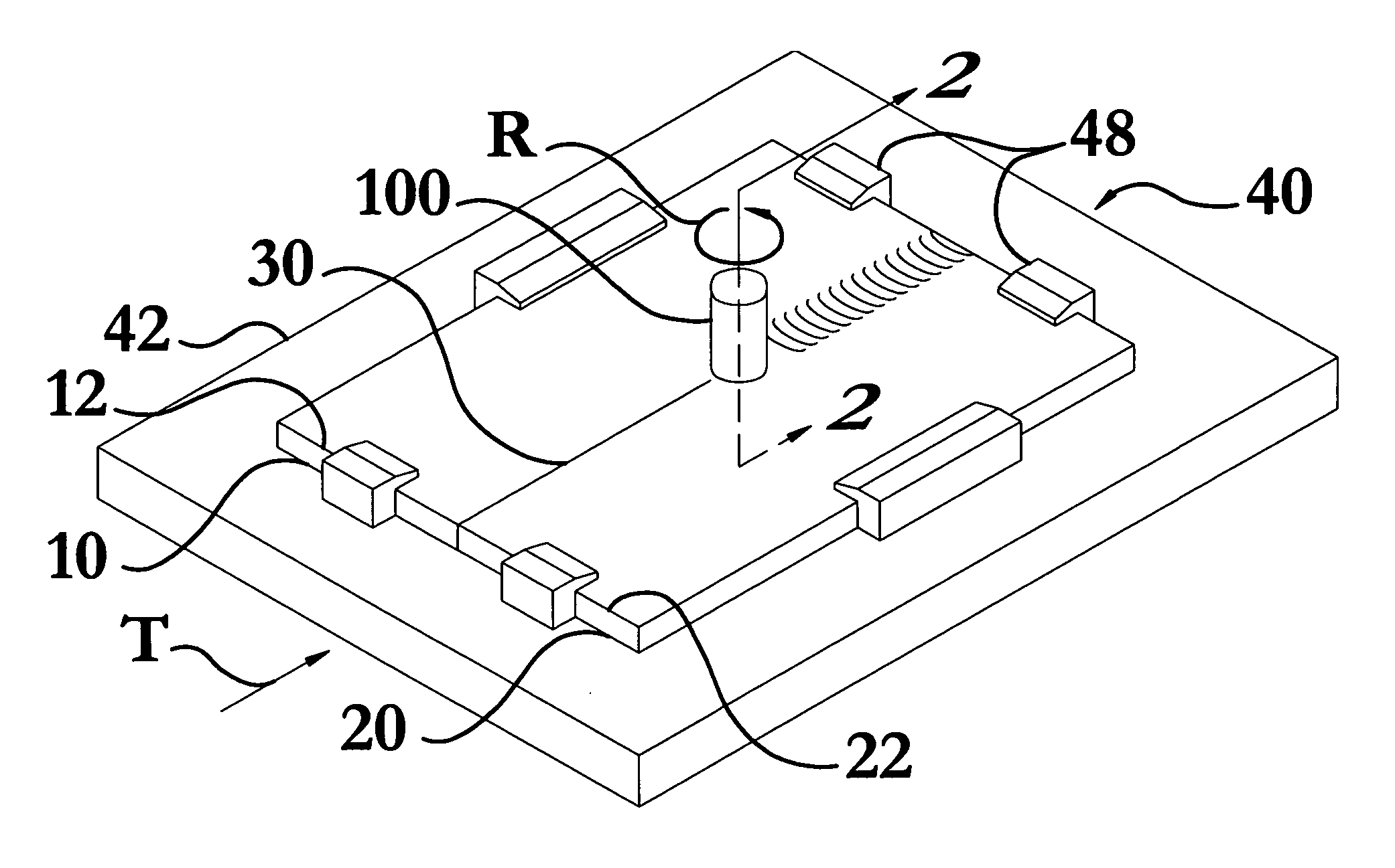
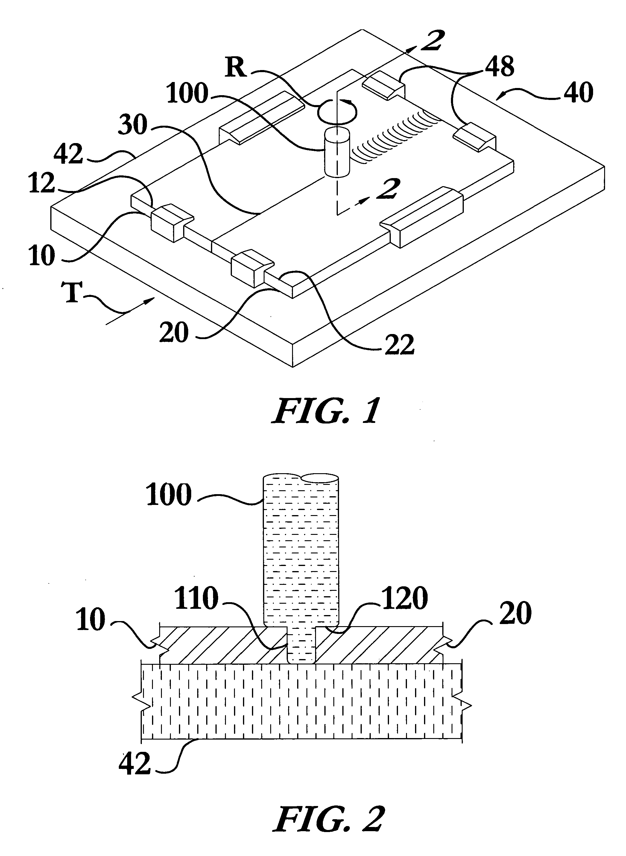
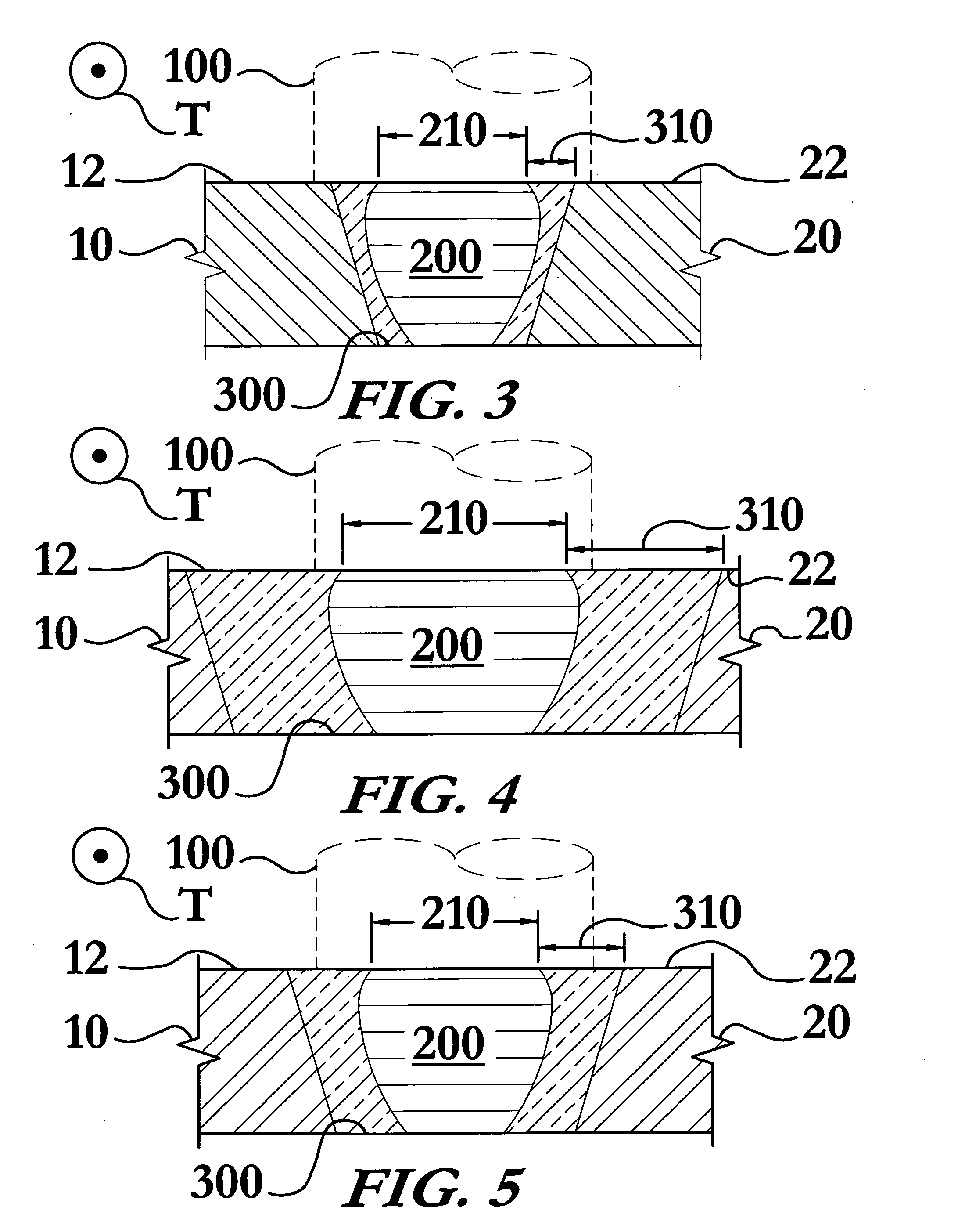
[0023] The friction stir welding travel axis load control method and apparatus enables a significant advance in the state of the art. The preferred embodiments of the method and apparatus accomplish this by new and novel methods that are configured in unique and novel ways and which demonstrate previously unavailable but preferred and desirable capabilities. The description set forth below in connection with the drawings is intended merely as a description of the presently preferred embodiments of the invention, and is not intended to represent the only form in which the present invention may be constructed or utilized. The description sets forth the designs, functions, means, and methods of implementing the invention in connection with the illustrated embodiments. It is to be understood, however, that the same or equivalent functions and features may be accomplished by different embodiments that are also intended to be encompassed within the spirit and scope of the invention.

[0024...


PUM

PropertyMeasurementUnit
lengthaaaaaaaaaa
sizeaaaaaaaaaa
dimensionsaaaaaaaaaa

Abstract

A friction stir welding (FSW) travel axis load control method and apparatus for controlling a travel axis load applied to a FSW setup during the joining of workpieces by FSW. The method and apparatus recognize that controlling certain attributes of a friction stir welding plasticized region are key to controlling the quality of the resulting weld. This invention controls any of a number of qualities associated with the plasticized region thereby producing welds having improved mechanical and aesthetic properties, as well as extending the life of the FSW tool. The method and apparatus may control the FSW process to obtain a predetermined optimum size of a heat affected zone. The plasticized region may be monitored in a number of ways including, but not limited to, force on the tool, torque applied to the tool, workpiece temperature, plasticized region physical dimension, as well as changing surface characteristics such as color and reflectivity.

Description

RELATED APPLICATIONS [0001] This application claims the benefit of U.S. provisional patent application Ser. No. 60 / 497,103, filed Aug. 22, 2003, all of which is incorporated by reference as if completely written herein.STATEMENT REGARDING FEDERALLY SPONSORED RESEARCH OR DEVELOPMENT [0002] This invention was not made as part of a federally sponsored research or development project. TECHNICAL FIELD [0003] The present invention relates to the field of friction stir welding; particularly, to a method and apparatus for monitoring and controlling the load applied to a friction stir welding tool during friction stir welding. BACKGROUND OF THE INVENTION [0004] Those in the wide ranging materials joining industries have recognized the benefits of friction stir welding (FSW) since its invention, only to be precluded from widespread application due to a number of factors. One such long-recognized need has been that of providing a system that monitors and controls the load placed upon a FSW too...

Claims


Application Information

Patent Timeline
Patent Type & Authority Applications(United States)
IPC IPC(8): B23K20/12
CPCB23K20/123
Inventor STOTLER, TIMOTHY V.TRAPP, TIMOTHY J.
Owner EDISON WELDING INSTITUTE INC
Why Eureka
Try Eureka