
UV lamp retainer system

a technology of uv lamp and retainer, which is applied in the field of uv lamp retainer system, can solve the problems of difficult to maintain accurate positioning of the bulb, difficulty in accurately positioning the bulb, etc., and achieves the effect of convenient removal and installation of uv lamps, accurate and repeatable positioning of lamps, and convenient replacement of uv lamps

Inactive Publication Date: 2005-02-24
NORDSON CORP
View PDF8 Cites 10 Cited by
  • Summary
  • Abstract
  • Description
  • Claims
  • Application Information

AI Technical Summary

Benefits of technology

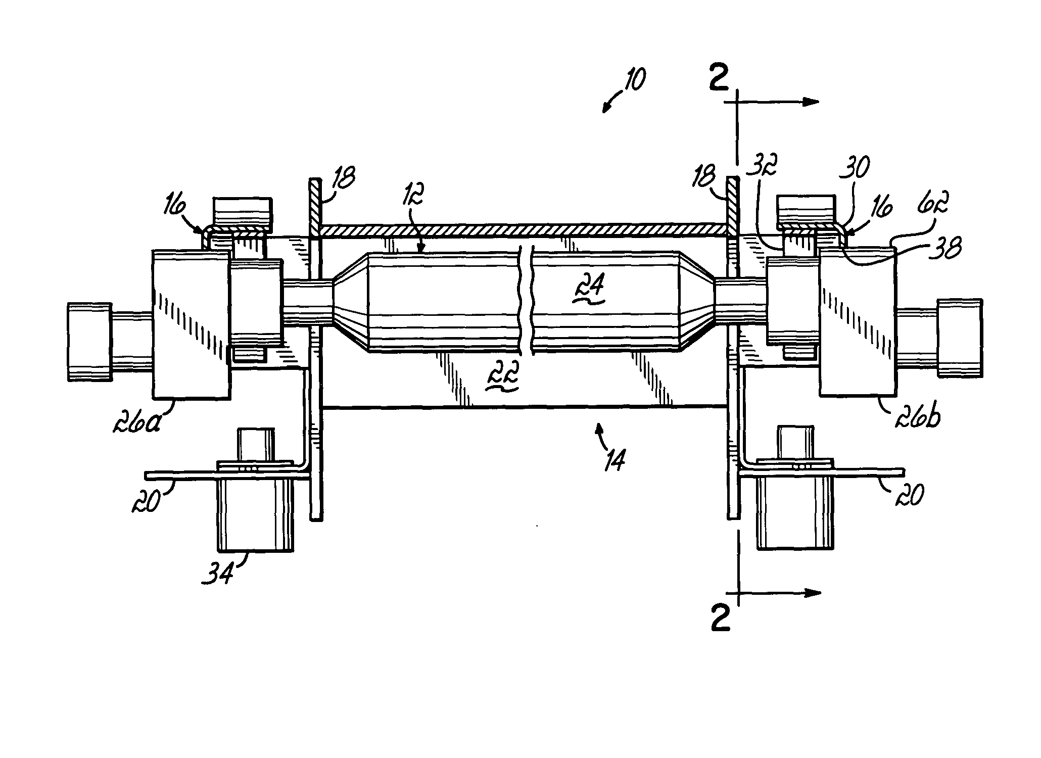
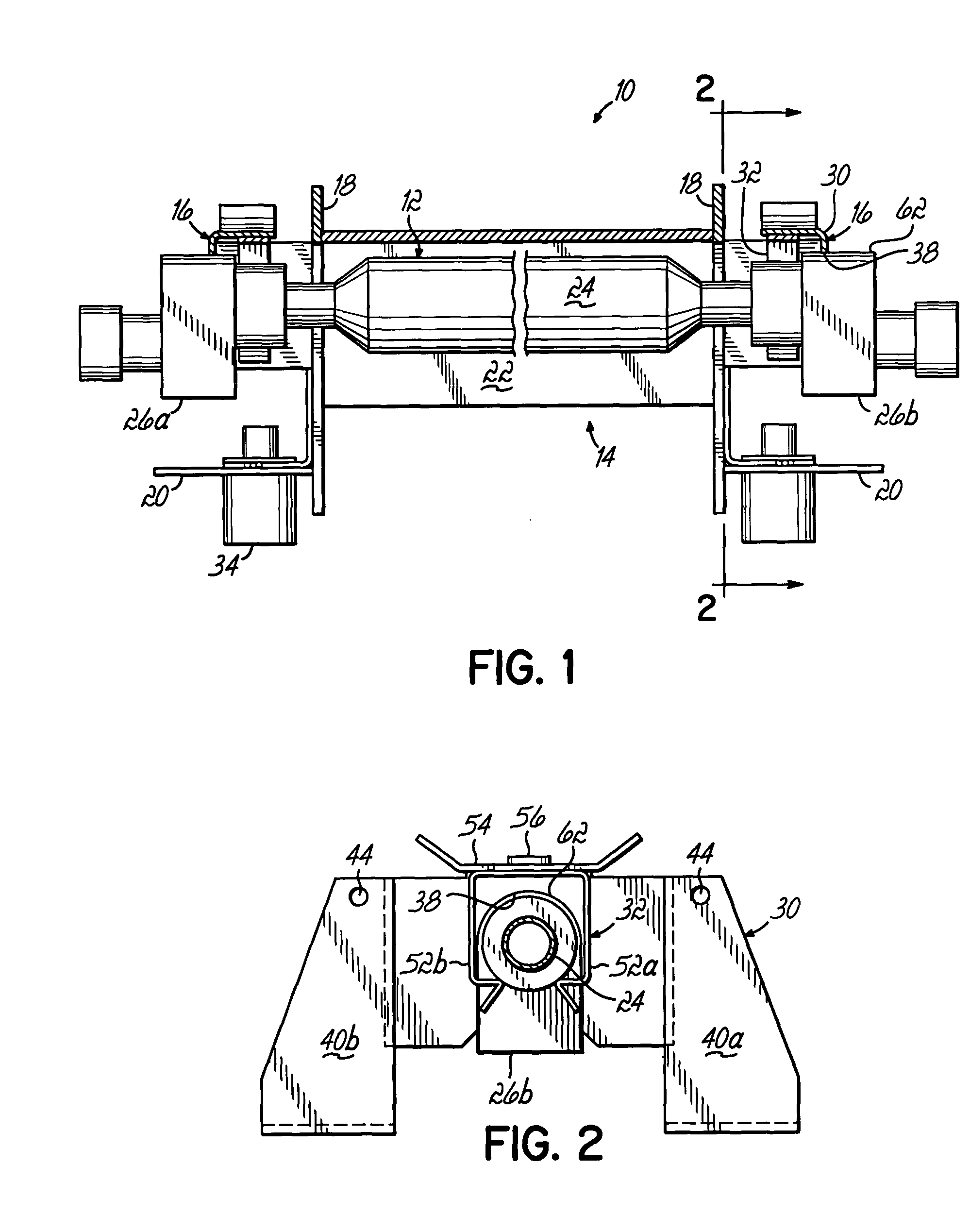
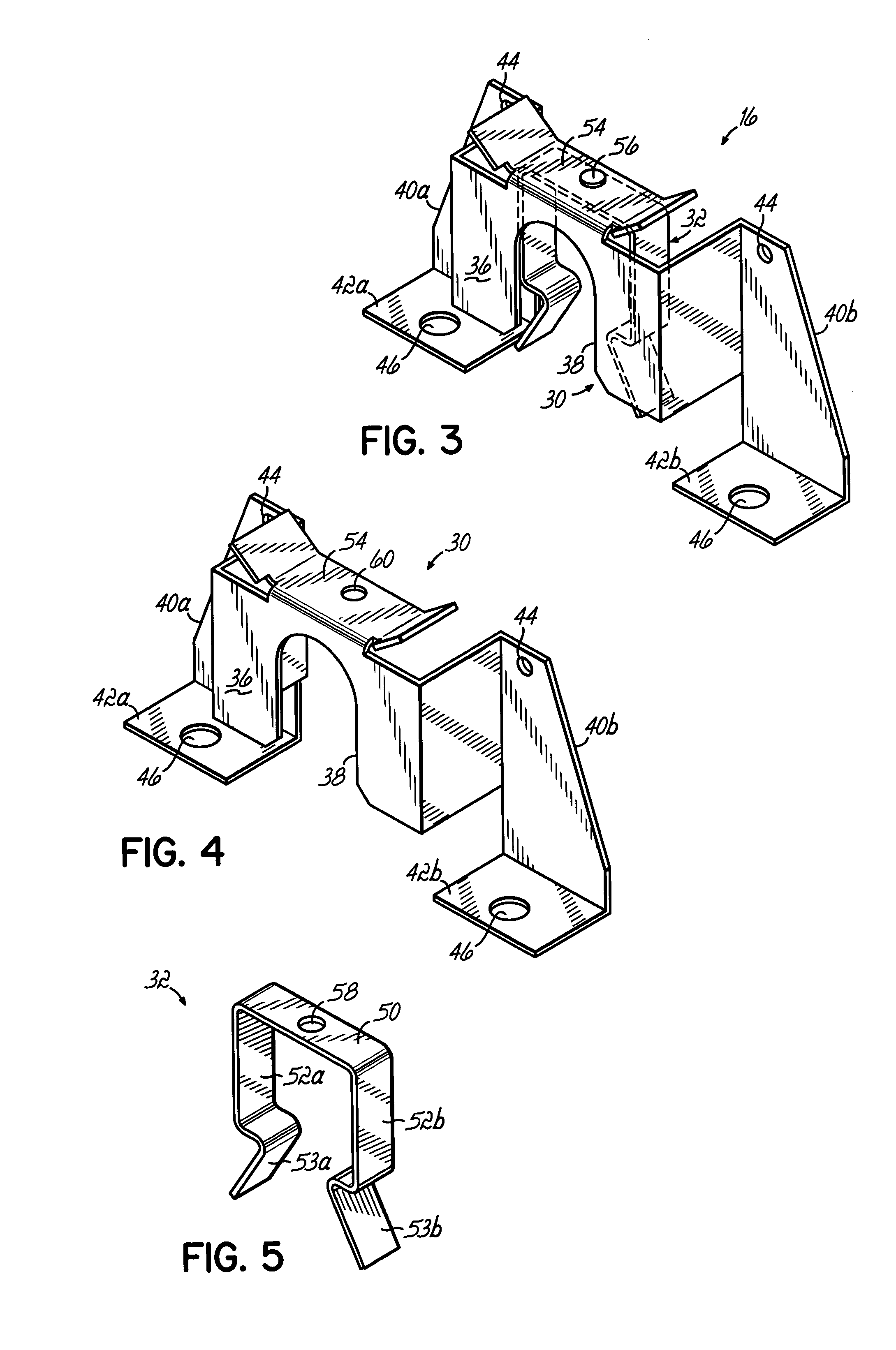
[0004] The present invention provides a lamp retainer that facilitates removal and installation of a UV lamp in a UV lamp system, to permit easy replacement of the UV lamp, while ensuring accurate and repeatable positioning of the lamp within a UV lamp housing. In one aspect of the invention, the lamp retainer includes a retainer bracket having a registration surface configured to engage a UV lamp and to provide a positive location for positioning the lamp with respect to the lamp housing and a reflector mounted within the housing. A retainer clip coupled to the bracket is configured to engage the lamp and bias the lamp toward the registration surface.

Problems solved by technology

One drawback of prior UV lamps systems has been the difficulty associated with accurately positioning the bulb.
Even when the bulb is initially installed in the correct position, the flexibility of supporting components often fail to maintain accurate positioning of the bulb, especially when exposed to the high heat generated by the UV lamp.
This problem is particularly troublesome for lamp assemblies which are fabricated from sheet metal components.

Method used


Image

  • UV lamp retainer system
  • UV lamp retainer system
  • UV lamp retainer system

Examples


Embodiment Construction

[0014] Referring to FIG. 1, there is shown an exemplary UV lamp system 10 including a UV lamp 12 supported in a housing 14 by an exemplary retainer assembly 16 in accordance with principles of the present invention. The housing 14 is configured to receive and support the components of the lamp system 10. In the exemplary embodiment shown, the housing 14 includes spaced vertical housing walls 18 and laterally extending housing support members 20 disposed on oppositely facing sides of the vertical walls 18. A lamp reflector 22 is secured to the housing 14, generally between the vertical walls 18 and is configured to reflect UV light emanating from the lamp 12 and direct it toward a substrate material (not shown) to be cured, dried, or otherwise affected by the UV light. The lamp 12 comprises an elongate quartz glass bulb 24 sealed at its ends by ceramic end caps 26a, 26b and containing an electrically excitable gas therein. Electrodes (not shown) positioned at respective ends of the b...


PUM


Abstract

A lamp retainer for a UV lamp system includes a retainer bracket having a registration surface configured to engage a UV lamp to thereby facilitate accurate and repeatable positioning of the lamp in a lamp housing. The lamp retainer further comprises a retainer clip couplable to the retainer bracket and configured to bias a UV lamp toward the registration surface. The retainer clip facilitates removal and installation of the UV lamp in the lamp housing.

Description

FIELD OF THE INVENTION [0001] The present invention relates generally to ultraviolet (UV) curing systems, and more particularly to a retainer for supporting a UV lamp in a UV lamp system. BACKGROUND OF THE INVENTION [0002] UV cure systems are widely used in industry to cure inks, paints, adhesives and coatings by ultraviolet radiation. Several types of UV lamps systems are available. One commonly used system utilizes mercury arc lamps to generate the necessary ultraviolet radiation. These lamps generally comprise a quartz bulb containing an electrically excitable gas, such as mercury, sealed within the bulb. The bulb is sealed by insulating end caps which also contain electrodes for electrically exciting or ionizing the gas to create and sustain a high voltage arc. Mercury arc lamps are typically supported in a lamp assembly by spring clips, whereby the lamp may be easily removed and replaced as required. The clips are shaped to engage the lamp and to support it at a desired locatio...

Claims


Application Information

Patent Timeline
Patent Type & Authority Applications(United States)
IPC IPC(8): F21V19/00F26B3/28H05B3/00
CPCF21V19/008H05B3/0052F26B3/28
Inventor SCHMITKONS, JAMES W.
Owner NORDSON CORP
Learn More