Fan motor speed control circuit

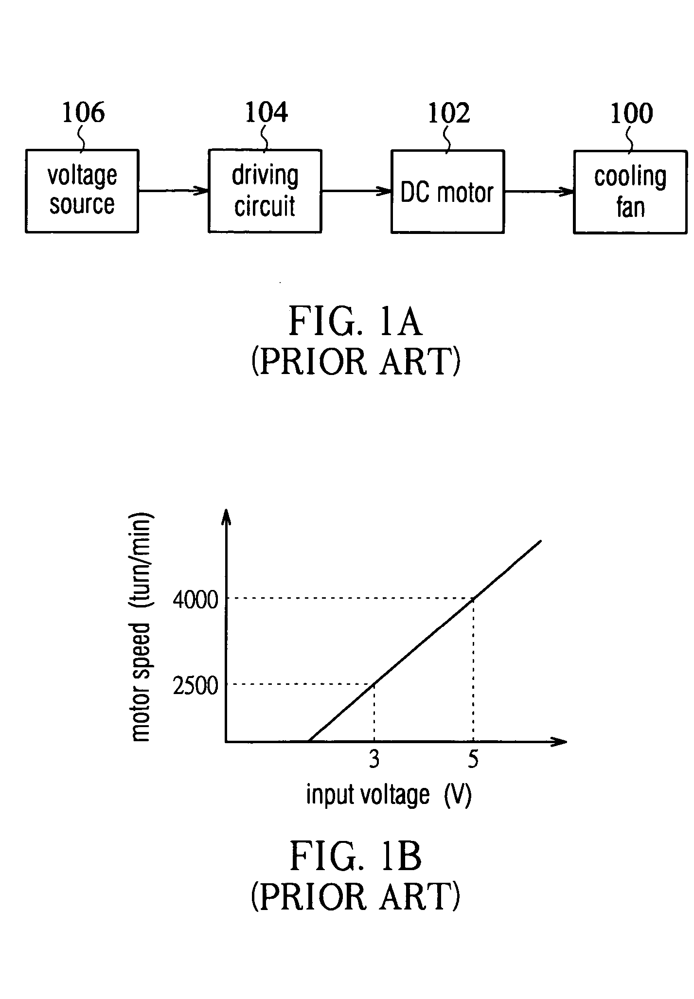
a technology of speed control circuit and fan motor, which is applied in the direction of motor/generator/converter stopper, dynamo-electric converter control, instruments, etc., can solve the problem of inability to achieve through the conventional dc motor 102 without changing the coil winding, and achieve the effect of easy adjustmen

Active Publication Date: 2005-02-24
DELTA ELECTRONICS INC
View PDF8 Cites 16 Cited by
  • Summary
  • Abstract
  • Description
  • Claims
  • Application Information

AI Technical Summary

Benefits of technology

[0009] Through the design of the invention, different current flow paths are created by the alternation of the on and off states for the transistors in the voltage division circuit and the speed modulator. As the current flows through the path in which the parallel resistors ar

Problems solved by technology

Hence, for instance, if a motor speed of 3000 rpm is required under an input voltage of 3 volts, i

Method used


Image

  • Fan motor speed control circuit
  • Fan motor speed control circuit
  • Fan motor speed control circuit

Examples


Embodiment Construction

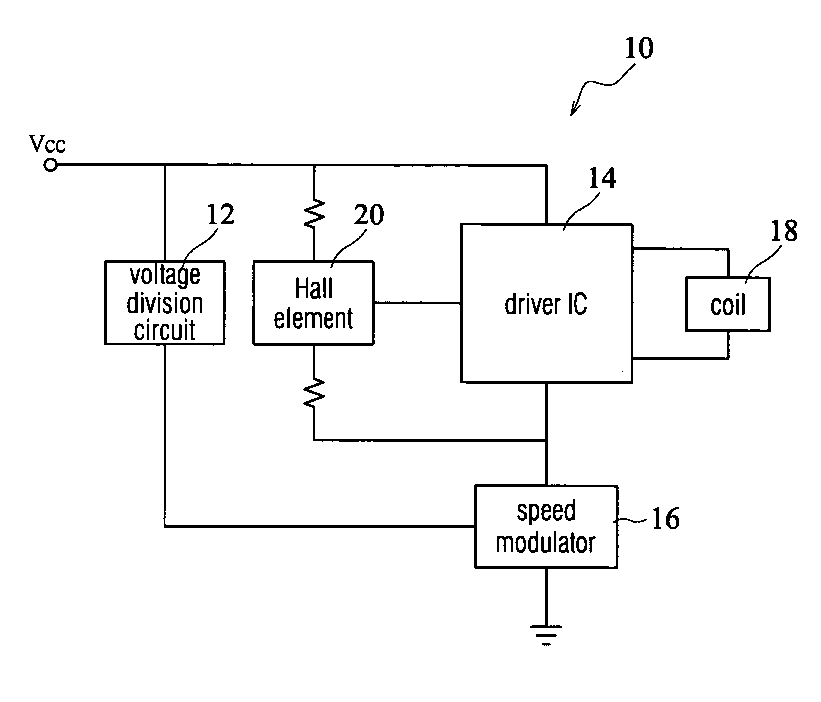
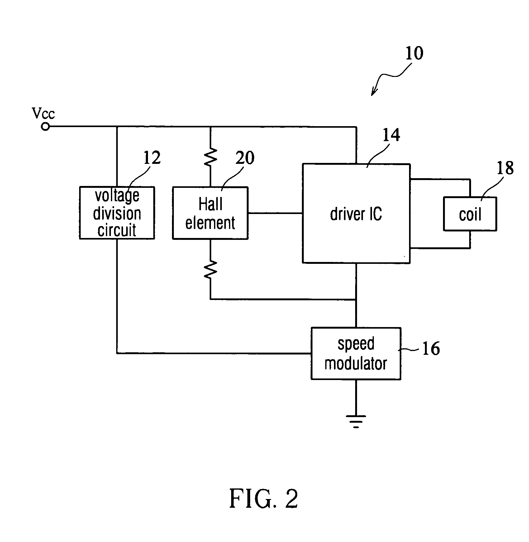
[0017] Referring to FIG. 2, a fan motor speed control circuit 10 includes a voltage division circuit 12, a driver integrated circuit (driver IC) 14 and a speed modulator 16. One of the input terminals of the driver IC 14 is connected to a hall element 20, which triggers the driver IC 14 to output an alternating pulse to induce the magnetic field in the coil 18.

[0018] As depicted in FIG. 3, the voltage division circuit 12 has a transistor Q1 and a plurality of resistors R1 to R4; the speed modulator 16 has a transistor Q2 and parallel resistors such as R5, R6, and R7. The driver IC 14 incorporates logic circuits consisting of H-bridges and transistors, and the hall element 20 is connected to an input terminal IN of the driver IC 14. The driver IC 14 outputs a drive signal to the coil 18 after the hall element 20 senses the magnetic polarity of the fan motor.

[0019] Furthermore, the resistor R1 is connected between a voltage source Vcc and the gate of the transistor Q1. The resistor ...


PUM


Abstract

A fan motor speed control circuit includes a driving circuit, a voltage division circuit, and a speed modulator. The voltage division circuit has a first transistor and a plurality of resistors and is connected between a voltage source and the driving circuit. The speed modulator has a second transistor and a plurality of parallel resistors and is connected between the voltage division circuit and the driving circuit. The current of the fan motor speed control circuit flows through a first path under a first input voltage generated from the voltage source and through a second path under a second input voltage larger than the first one; the parallel resistors are in the second path such that the current value passing through the driving circuit varies according to the resulting resistance value of the parallel resistors.

Description

BACKGROUND OF THE INVENTION [0001] (a) Field of the Invention [0002] The invention relates to a speed control circuit and, more particularly, to a speed control circuit for enabling a fan motor to have various speeds at any selected voltage. [0003] (b) Description of the Related Art [0004] Referring to FIG. 1A, a conventional cooling fan 100 and a driving circuit 104 is connected to a direct current (DC) motor 102. The voltage of the driving circuit 104 is provided by a voltage source 106, and the driving circuit 104 feeds a signal, often a current signal, to the DC motor 102 to activate it. Typically, the speeds of the cooling fan 100 and the motor 102 are equal because the cooling fan 100 is linked with the motor 102. [0005] In a conventional manner, the fan speed is fixed at any selected voltage, and thus the coil winding of the DC motor 102 must be changed to alter the fan speed at the voltage. [0006] For the same coil winding, the relation between the motor speed and input volt...

Claims


Application Information

Patent Timeline
IPC IPC(8): H02P6/06H02P6/08H02P6/26H02P7/00
CPCY10S388/934H02P6/002H02P6/28
Inventor LIN, YU-LIANGHUANG, YUEH-LUNGLEI, TSUNG-YUHSIEH, JU-WENHUANG, WEN-SHI
Owner DELTA ELECTRONICS INC
Why Eureka
Try Eureka