Electromagnetic relay

a technology of electromagnets and relays, applied in the field of electromagnet relays, can solve the problems of reducing the space for disposing coils on the base, reducing the magnetic attractive force, etc., and achieve the effect of increasing the magnetic attractive force of an electromagnet without increasing the external dimension, stable operation characteristics, and high structural reliability

Active Publication Date: 2005-02-24
FUJITSU COMPONENENT LTD
View PDF4 Cites 17 Cited by
  • Summary
  • Abstract
  • Description
  • Claims
  • Application Information

AI Technical Summary

Benefits of technology

[0008] It is an object of the present invention to provide an electromagnetic relay capable of ensuring a desired insulation distance between an electromagnet assembly and a contact section, and of increasing

Problems solved by technology

As a result, there is a problem in that the external dimension of the electromagnetic relay as seen in a radial direction of the coil (or a height dimension) is increased, o

Method used


Image

  • Electromagnetic relay
  • Electromagnetic relay
  • Electromagnetic relay

Examples


Embodiment Construction

[0028] The embodiments of the present invention are described below, in detail, with reference to the accompanying drawings. In the drawings, the same or similar components are denoted by common reference numerals.

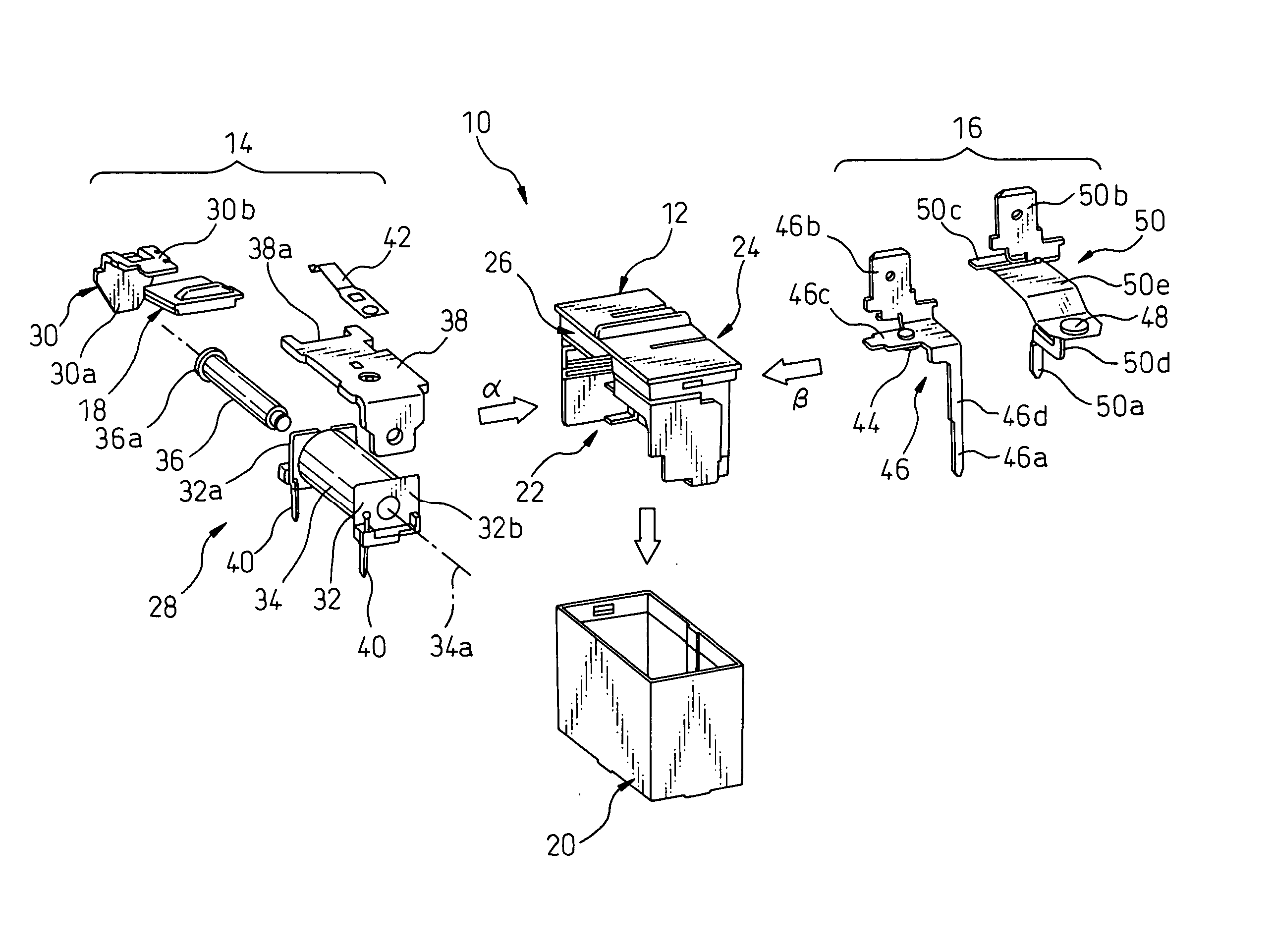
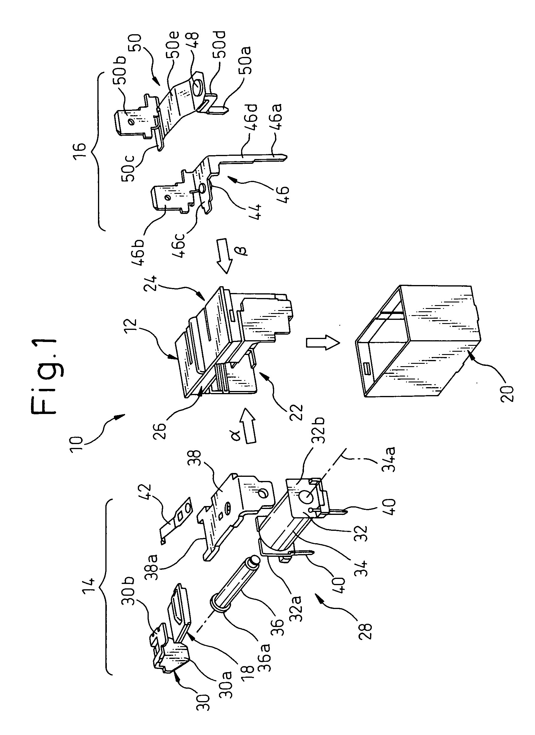
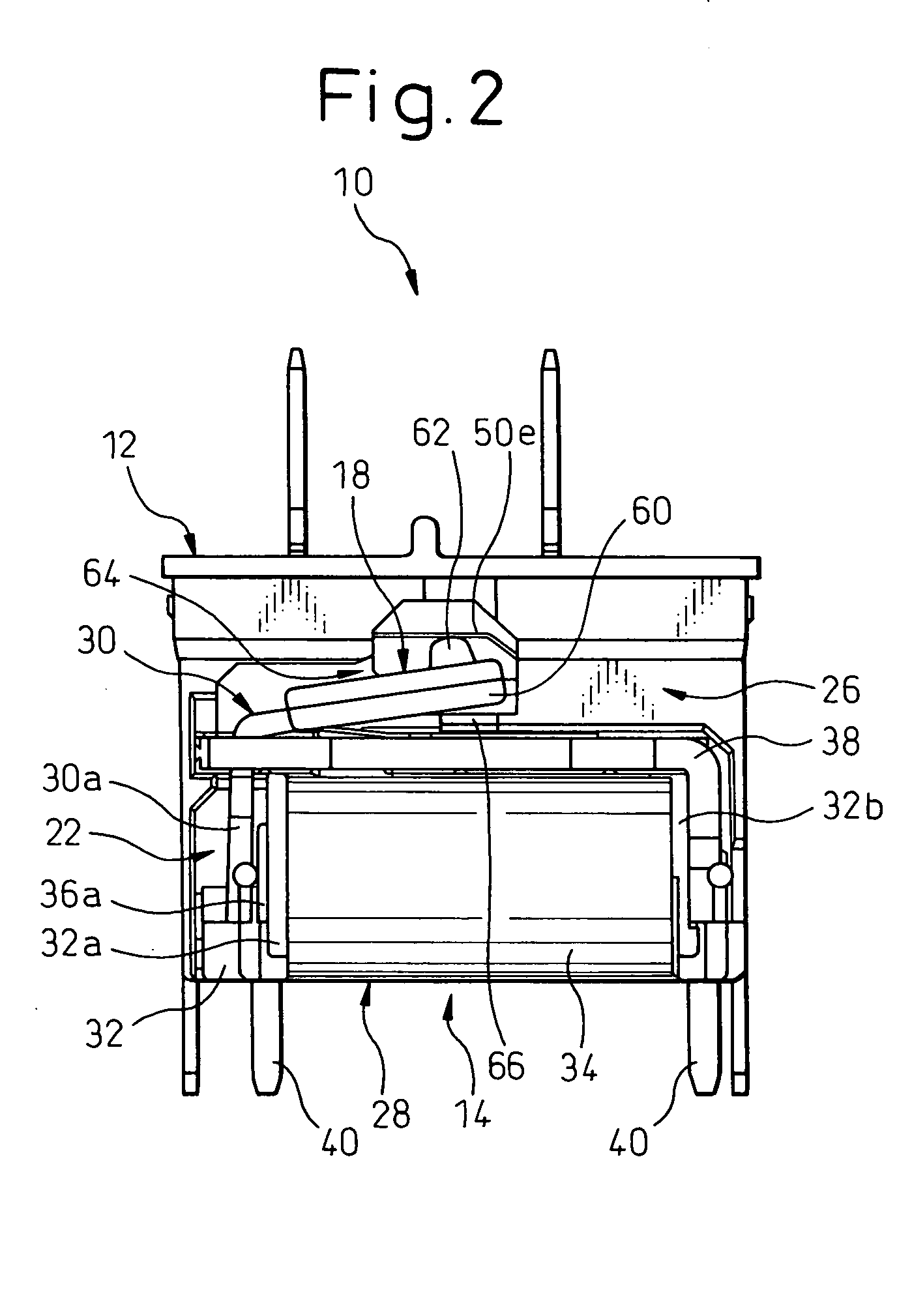
[0029] Referring to the drawings, FIG. 1 is an exploded perspective view of an electromagnetic relay 10 according to one embodiment of the present invention, and FIGS. 2 and 3 are front views respectively showing the electromagnetic relay 10 in mutually opposite directions. The electromagnetic relay 10 includes a base 12, an electromagnet assembly 14 incorporated in the base 12, a contact section 16 incorporated in the base 12 and is separated from the electromagnet assembly 14 at a predetermined insulation distance or clearance, an actuating member 18 arranged between the electromagnet assembly 14 and the contact section 16 and shiftable under the action of the electromagnet assembly 14 for actuating the contact section 16 to be opened or closed, and a hollow box-shaped ...


PUM


Abstract

An electromagnetic relay including a base having a first receptacle, a second receptacle and a partition wall defining the first and second receptacles on mutually opposite sides of the partition wall. The partition wall includes a major part and an auxiliary part, the major part being provided with a local opening. An electromagnet assembly is received in the first receptacle of the base and includes an electromagnet and an armature. The armature includes an extending portion extending in a direction toward the second receptacle of the base through the local opening of the partition wall. The auxiliary part of the partition wall is disposed between the electromagnet and the extending portion of the armature. A contact section is received in the second receptacle of the base. An actuating member is arranged between the electromagnet assembly and the contact section, and includes an envelope part for enclosing at least a part of the extending portion of the armature. When the contact section is opened, the envelope part of the actuating member is supported by the auxiliary part of the partition wall.

Description

BACKGROUND OF THE INVENTION [0001] 1. Field of the Invention [0002] The present invention relates to an electromagnetic relay. [0003] 2. Description of the Related Art [0004] In an electromagnetic relay including an electromagnet assembly and a contact section acting to open or close in accordance with the operation of the electromagnet assembly, both incorporated in a common base, it is known that the components of the electromagnet assembly and the components of the contact section are assembled or inserted into the mutually opposite sides of the base, for the purpose of ensuring an electrical insulation distance or clearance in terms of “creepage” (or a so-called creeping distance) between the electromagnet assembly and the contact section (see, e.g., Japanese Unexamined Patent Publication (Kokai) No. 11-213833 (JP-A-11-213833)). In the electromagnetic relay described in JP-A-11-213833, the base is provided with a first receptacle for receiving the electromagnet assembly, a secon...

Claims


Application Information

Patent Timeline
IPC IPC(8): H01H50/26H01H11/00H01H50/02H01H50/04H01H50/10H01H50/14
CPCH01H11/0031H01H50/14H01H50/043H01H50/026
Inventor TAKANO, SATOSHIAOKI, SHIGEMITSU
Owner FUJITSU COMPONENENT LTD
Why Eureka
Try Eureka