Method for controlling electro-optic display

a technology of electro-optic display and display screen, which is applied in the direction of instruments, static indicating devices, etc., can solve the problems of preventing their widespread use, affecting the service life of these displays, and consuming power during such constant refresh of images,

Active Publication Date: 2005-02-24
E INK CORPORATION
View PDF99 Cites 121 Cited by
  • Summary
  • Abstract
  • Description
  • Claims
  • Application Information

AI Technical Summary

Benefits of technology

[0037] the common electrode control means being arranged to apply to the common electrode a first voltage when the display

Problems solved by technology

Nevertheless, problems with the long-term image quality of these displays have prevented their widespread usage.
For example, particles that make up electrophoretic displays tend to settle, resulting in inadequate service-life for these displays.
The power consumed during such constant refreshment of an image is a major drain on the battery.
However, in practice this would lead to a steady state DC bias current being applied to the electro-optic medium.
This current flow will in turn generate a voltage across the electro-optic medium, and this voltage is undesirable because such it can disturb the optical state of the electro-optic medium during the non-writing period and can also lead to reduced material lifetime and the buildup of charges in the electro-optic medium that will adversely affect the optical states of subsequent images after scanning is resumed.
(It has been shown that at least some electro-optic media are adversely affected if the current therethrough is not DC balanced over the long term, and that such DC imbalance may lead to reduced working lifetime and other undesirable effects.)
Furthermore, although at first glance it might appear that powering down the driver circuitry in preparation

Method used


Image

  • Method for controlling electro-optic display
  • Method for controlling electro-optic display
  • Method for controlling electro-optic display

Examples


Embodiment Construction

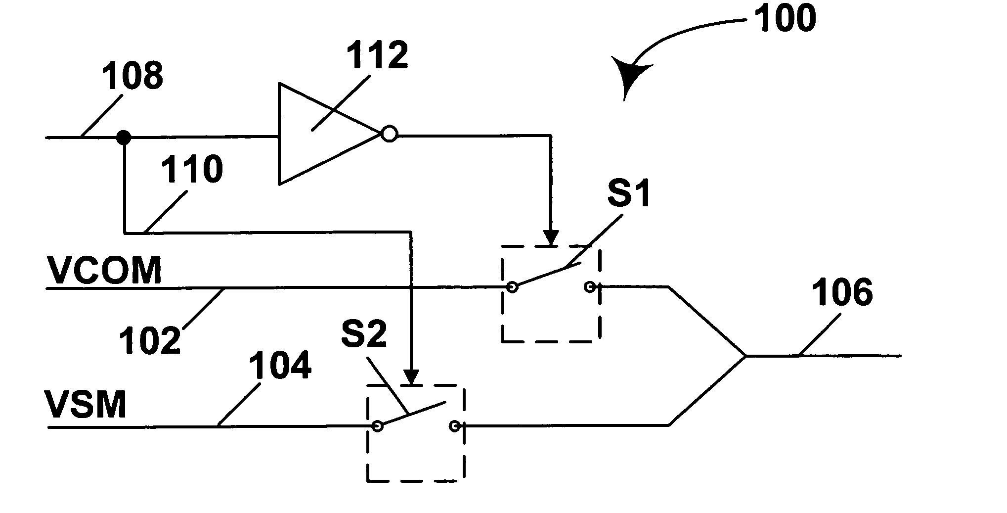
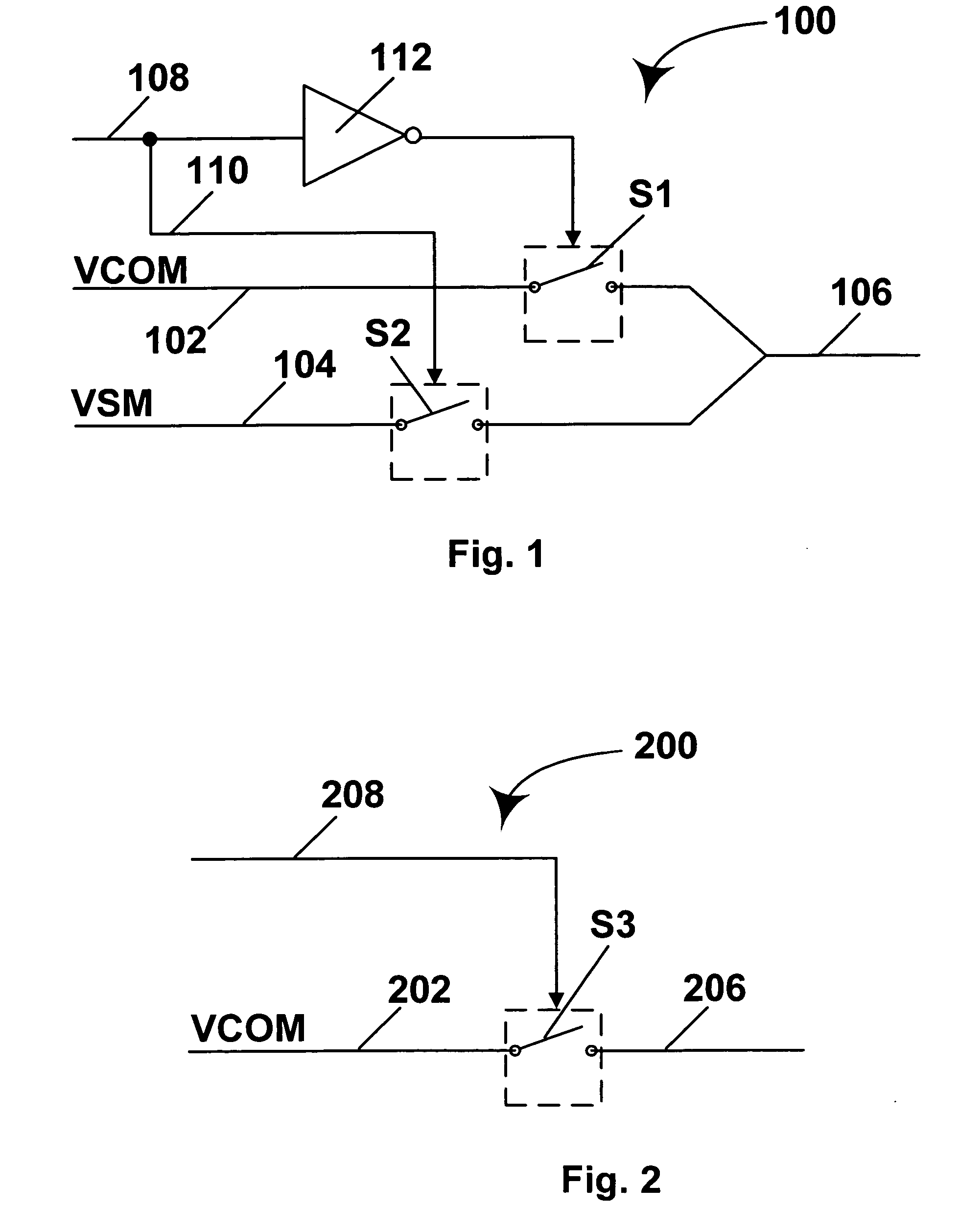
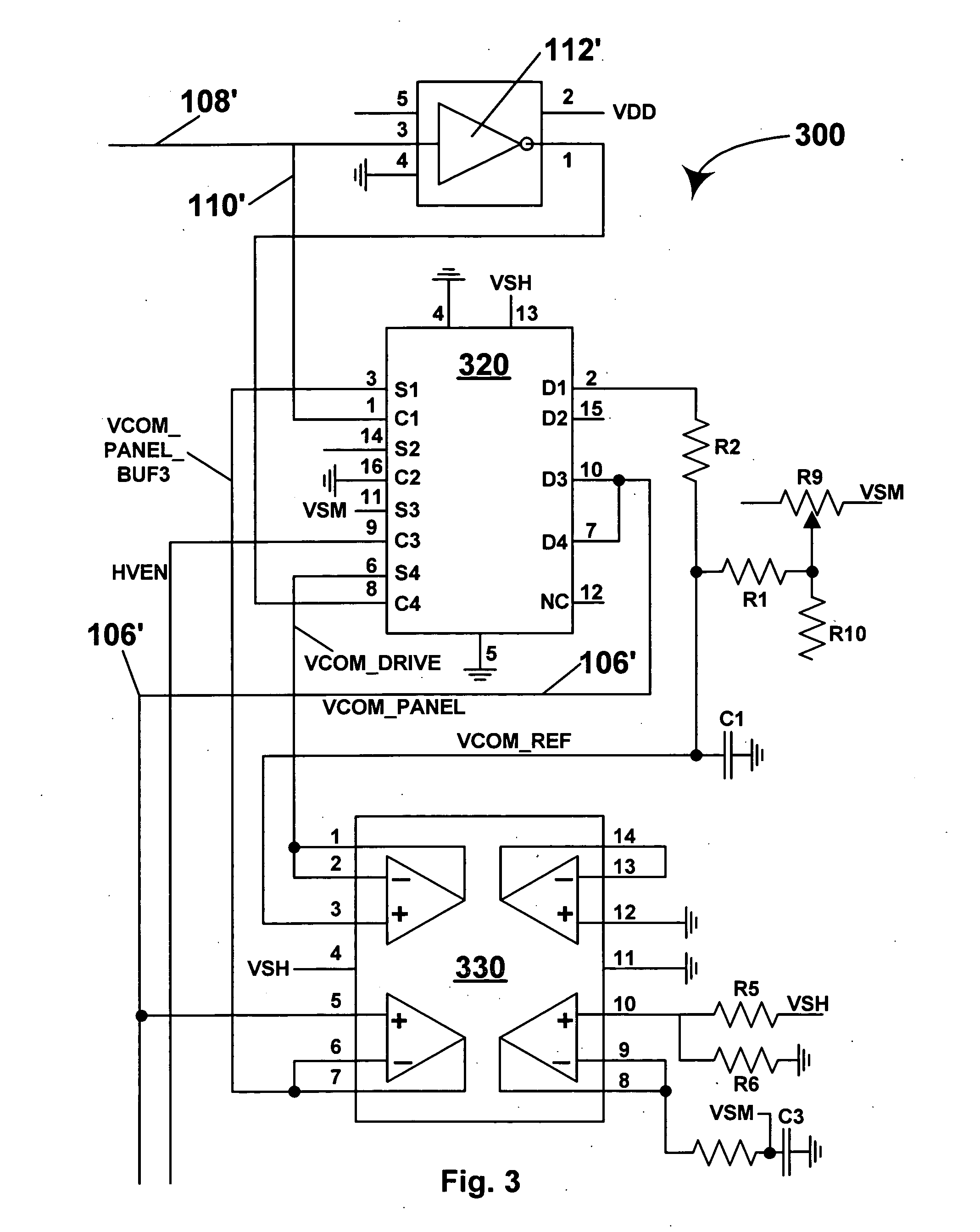
[0100] As already indicated, the present invention has several different aspects relating displays and methods for controlling electrode voltage in electro-optic displays, and to measuring and correcting for feedthrough voltage in such displays. The various aspects of the invention will generally be described separately below, but it will be appreciated that a single display may make use of more than one aspect of the present invention; for example, the display of FIG. 6 makes use of both the floating common electrode display and feedthrough voltage measuring aspects of the invention.

[0101] As discussed above, the main problem with which the present invention seeks to deal is the difference caused by gate feedthrough between the voltages which the driver circuits apply to the non-linear elements of an electro-optic display (these may hereinafter be called “column driver voltages” since as already indicated it is conventional though essentially arbitrary to select one row of pixels ...


PUM


Abstract

An electro-optic display comprises a bistable electro-optic medium, a plurality of pixel electrodes, with associated non-linear elements, and a common electrode, disposed on opposed sides of the electro-optic medium. The display has a writing mode, in which at least two different voltages are applied to different pixel electrodes, and a non-writing mode in which the voltages applied to the pixel electrodes are controlled so that any image previously written on the electro-optic medium is substantially maintained. The display is arranged to apply to the common electrode a first voltage when the display is in its writing mode and a second voltage, different from the first voltage, when the display is in its non-writing mode.

Description

REFERENCE TO RELATED APPLICATIONS [0001] This application claims benefit of Provisional Applications Ser. Nos. 60 / 481,258 and 60 / 481,262, both filed Aug. 19, 2003. [0002] This application is also related to (1) copending application Ser. No. 10 / 065,795, filed Nov. 20, 2002 (Publication No. 2003 / 0137521), which is itself is a continuation-in-part of application Ser. No. 09 / 561,424, filed Apr. 28, 2000 (now U.S. Pat. No. 6,531,997), which is itself a continuation-in-part of copending application Ser. No. 09 / 520,743, filed Mar. 8, 2000 (now U.S. Pat. No. 6,504,524). Application Ser. No. 10 / 065,795 also claims priority from the following Provisional Applications: (a) Ser. No. 60 / 319,007, filed Nov. 20, 2001; (b) Ser. No. 60 / 319,010, filed Nov. 21, 2001; (c) Ser. No. 60 / 319,034, filed Dec. 18, 2001; (d) Ser. No. 60 / 319,037, filed Dec. 20, 2001; and (e) Ser. No. 60 / 319,040, filed Dec. 21, 2001; (2) application Ser. No. 10 / 249,973, filed May 23, 2003, which is a continuation-in-part of the...

Claims


Application Information

Patent Timeline
IPC IPC(8): G09GG09G3/34G09G3/36
CPCG09G3/20G09G3/34G09G3/344G09G2300/0473G09G3/3655G09G2310/0275G09G2320/0219G09G3/3651G09G2300/08
Inventor GATES, HOLLY G.AMUNDSON, KARL R.
Owner E INK CORPORATION
Why Eureka
Try Eureka