Scatterometry to simultaneously measure critical dimensions and film properties

Active Publication Date: 2005-02-24
THERMA WAVE INC
View PDF18 Cites 15 Cited by
  • Summary
  • Abstract
  • Description
  • Claims
  • Application Information

AI Technical Summary

Benefits of technology

The shallow angle of incidence gives the ellipsometer 200 a relatively small spot size. At the s

Problems solved by technology

The ellipsometry case is more difficult because sensitivity to film attributes improves as angle of incidence increases.
Un

Method used


Image

  • Scatterometry to simultaneously measure critical dimensions and film properties
  • Scatterometry to simultaneously measure critical dimensions and film properties
  • Scatterometry to simultaneously measure critical dimensions and film properties

Examples


Example

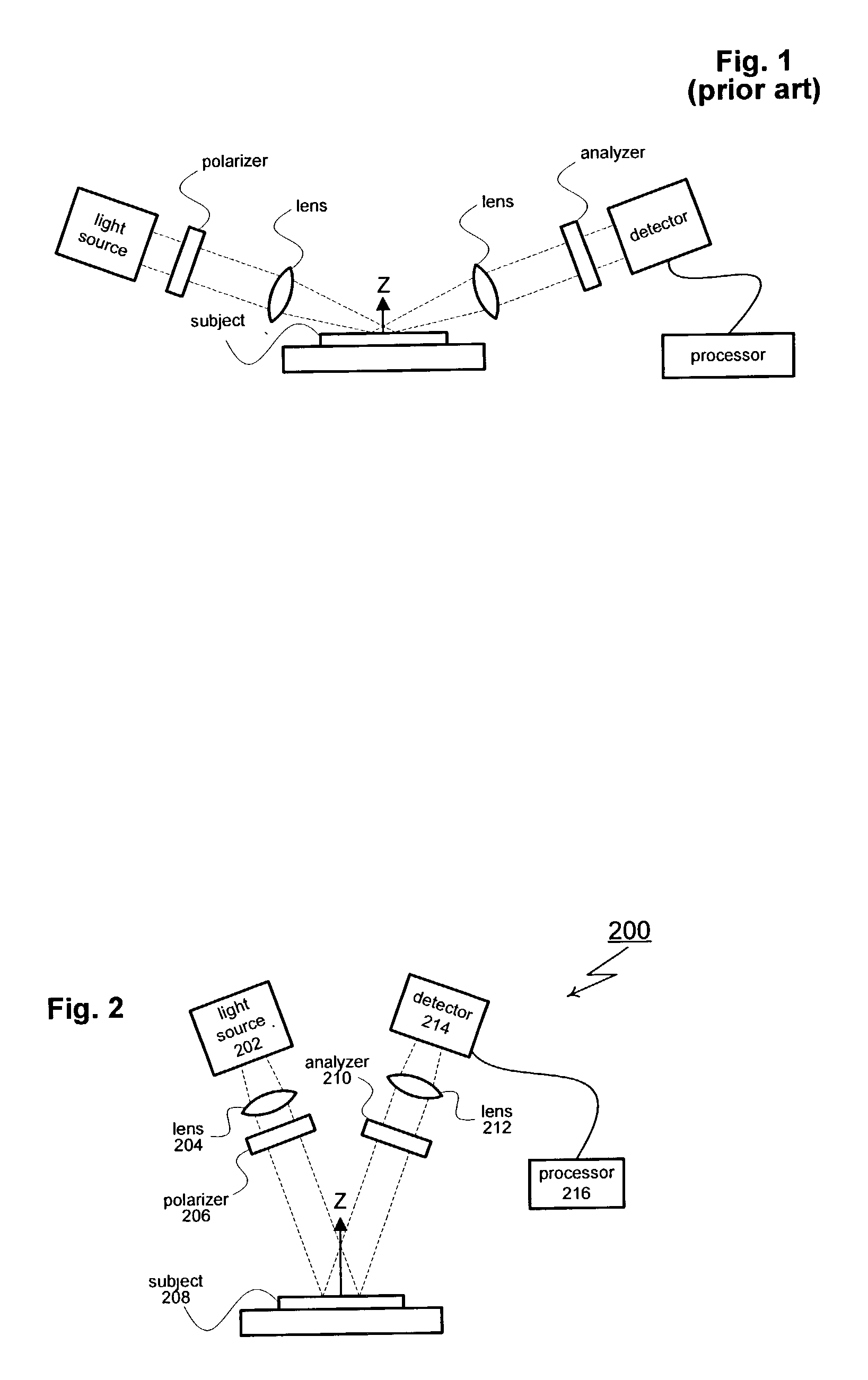
As shown in FIG. 2, a first aspect of the present invention includes an ellipsometer generally designated 200. Ellipsometer 200 includes an illumination source 202 that creates a mono or polychromatic probe beam. The probe beam is focused by one or more lenses 204 (or other appropriate optical elements such as mirrors) and passed through a polarizer 206. The polarizer 206 imparts a known polarization state to the probe beam. The polarized probe beam creates an illumination spot on the surface of the subject under test 208. An image of the illumination spot (or a portion of the illumination spot) passes through an analyzer 210 and lens 212 before reaching a detector 214. Lens 212 may be selected from a range of different components including achromatic lenses and focusing mirrors. The detector 214 captures (or otherwise processes) the received image. A processor 216 analyzes the data collected by the detector 214.

For the specific example of FIG. 2, the probe beam is directed at an...


PUM


Abstract

An ellipsometer includes a light source for generating a probe beam of polychromatic light for interacting with a sample. A polarizer is used to impart a known polarization state to the probe beam and the polarized probe beam is directed against the sample at a shallow angle of incidence. A rotating compensator is used to impart phase retardations to the polarization state of the reflected probe beam. After passing through the compensator, the probe beam passes through a second polarizer (analyzer). After leaving the analyzer, the probe beam is received by a detector. The detector translates the received probe beam into a signal that includes DC, 2ω and 4ω signal components (where ω is the angular velocity of the rotating compensator). A processor analyzes the signal using the DC, 2ω and 4ω components allowing simultaneous evaluation of both critical dimensions and film parameters.

Description

TECHNICAL FIELD The subject invention relates to ellipsometry systems used to inspect and analyze semiconductor wafers. In particular, the present invention relates to systems for simultaneously measuring critical dimensions and film properties of subject wafers. BACKGROUND OF THE INVENTION As geometries continue to shrink, manufacturers have increasingly turned to optical techniques to perform non-destructive inspection and analysis of semi-conductor wafers. The basis for these techniques is the notion that a subject may be examined by analyzing the reflected energy that results when a probe beam is directed at the subject. Ellipsometry and reflectometry are two examples of commonly used optical techniques. For the specific case of ellipsometry, changes in the polarization state of the probe beam are analyzed. Reflectometry is similar, except that changes in magnitude are analyzed. Scatterometry is a related technique that measures the diffraction (optical scattering) that the su...

Claims


Application Information

Patent Timeline
IPC IPC(8): G01B11/06G01N21/21G01N21/84
CPCG01B11/0641G01N2021/213G01N21/8422G01N21/211
Inventor OPSAL, JON
Owner THERMA WAVE INC
Why Eureka
Try Eureka