Laser desorption electrospray ionization source
- Summary
- Abstract
- Description
- Claims
- Application Information
AI Technical Summary
Benefits of technology
Problems solved by technology
Method used
Image
Examples
example 1
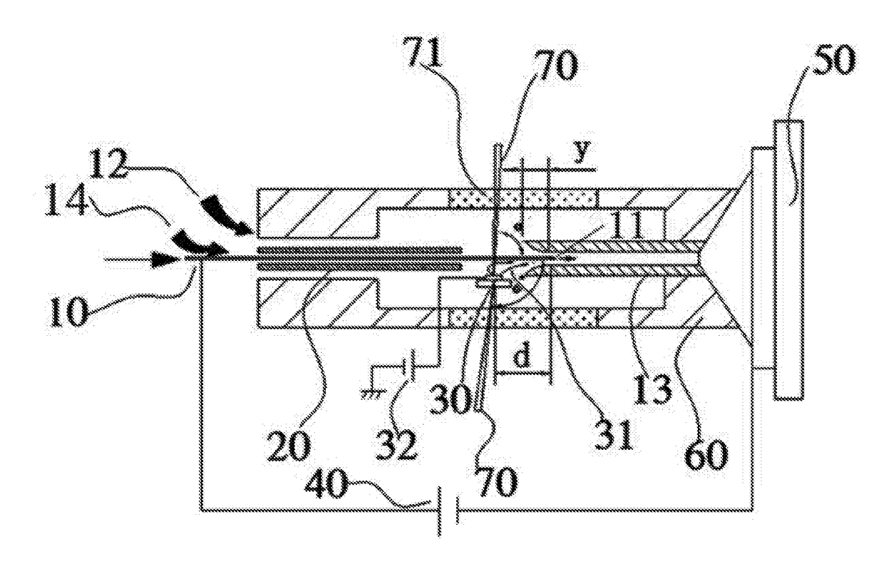
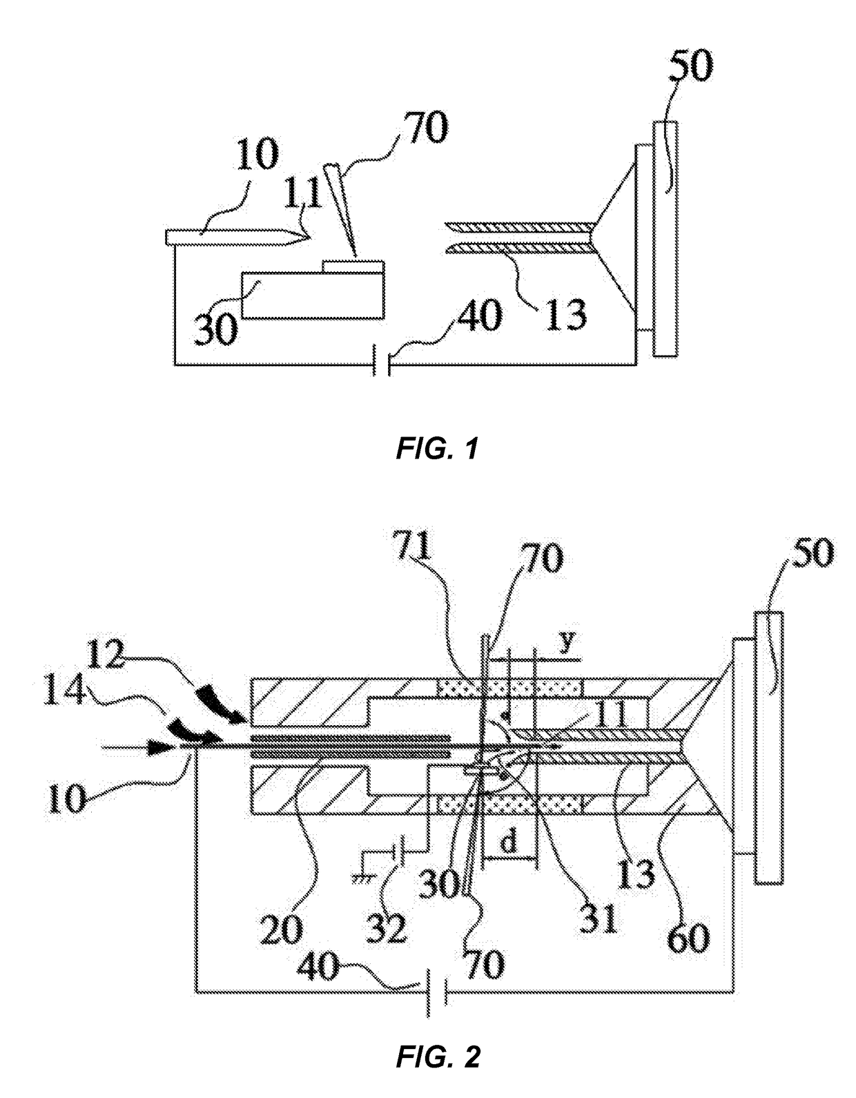
[0031]FIG. 2 shows an example laser desorption electrospray ionization source. The ionization source includes a hollow emission needle 10, an ion transfer tube 13, and a sample platform 30 for receiving samples on a sample target. A laser is used for producing laser pulses 70 directed to the sample target. One end of the hollow emission needle 10 provides a liquid intake and the other end has an electrospray nozzle. A first end of the ion transfer tube 13 is opposite the nozzle of the hollow emission needle 10 and provides an entrance, while a second end is in communication with a vacuum chamber of a mass spectrometer 50. An ESI source supply apparatus 40 is electrically connected between the mass spectrometer 50 and the hollow emission needle 10. The sample platform 30 is located at the entrance of the ion transfer tube 13, such that the impact point of laser pulses 70 on the sample target is located behind (to the left of in FIG. 2) the nozzle of the hollow emission needle 10. A h...
example 2
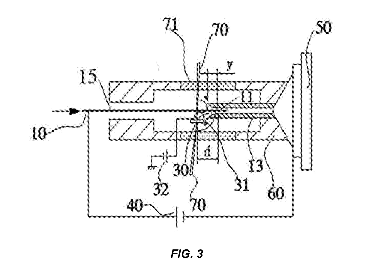
[0034]FIG. 3 shows another example embodiment of a laser desorption electrospray ionization source. The ionization source of FIG. 3 includes a hollow emission needle 10, an ion transfer tube 13, and a sample platform 30 for receiving samples on a sample target. A laser is used for producing laser pulses 70 directed to the sample target. A source working chamber 60 is fitted outside the hollow emission needle 10, the ion transfer tube 13, and the sample platform 30. One end of the source working chamber 60 connects to the mass spectrometer 50. One end of the hollow emission needle 10 provides a liquid intake and the other end has an electrospray nozzle. A first end of the ion transfer tube 13 is opposite the nozzle of the hollow emission needle 10 and provides an entrance, while a second end is in communication with a vacuum chamber of a mass spectrometer 50. An ESI source supply apparatus 40 is electrically connected between the mass spectrometer 50 and the hollow emission needle 10...
example 3
[0037]As shown in the laser desorption electrospray ionization source FIG. 2, the ionization source includes a hollow emission needle 10, an ion transfer tube 13, and a sample platform 30 for receiving samples on a sample target. A laser is used for producing laser pulses 70 directed to the sample target. A source working chamber 60 is fitted outside the hollow emission needle 10, the ion transfer tube 13, and the sample platform 30. One end of the source working chamber 60 connects to the mass spectrometer 50. One end of the hollow emission needle 10 provides a liquid intake and the other end has an electrospray nozzle. A first end of the ion transfer tube 13 is opposite the nozzle of the hollow emission needle 10 and provides an entrance, while a second end is in communication with a vacuum chamber of a mass spectrometer 50. An ESI source supply apparatus 40 is electrically connected between the mass spectrometer 50 and the hollow emission needle 10. The sample platform 30 is loca...
PUM
 Abstract
Description
Claims
Application Information
 - R&D
- Intellectual Property
- Life Sciences
- Materials
- Tech Scout
- Unparalleled Data Quality
- Higher Quality Content
- 60% Fewer Hallucinations
Browse by: Latest US Patents, China's latest patents, Technical Efficacy Thesaurus, Application Domain, Technology Topic, Popular Technical Reports.
© 2025 PatSnap. All rights reserved.Legal|Privacy policy|Modern Slavery Act Transparency Statement|Sitemap|About US| Contact US: help@patsnap.com


