
Toner container and image forming apparatus using the same

a technology which is applied in the field of toner container and image forming apparatus using the same, can solve the problems of high cost, complicated structure of toner container, and inability to meet the needs of users, and achieves the effects of preventing toner from leaking, simple structure, and easy handling

Inactive Publication Date: 2005-02-24
RICOH KK
View PDF99 Cites 23 Cited by
  • Summary
  • Abstract
  • Description
  • Claims
  • Application Information

AI Technical Summary

Benefits of technology

[0009] It is an object of the present invention to provide a toner container or similar powder container extremely simple in structure and easy to handle while surely preventing toner from leaking, and an image forming apparatus using the same.

Problems solved by technology

While a toner container mounted to an image forming apparatus is usually replaced by the user, the replacement often causes toner to scatter and is awkward to perform.
However, this kind of toner container has sophisticated, expensive structure.
However, the problem with the sponge seal is that the elastic restoring force is apt to decrease due to, e.g., creep when the seal hardens in a low-temperature environment or due to aging.
The sponge seal reduced in restoring force often causes the toner to leak when the toner is pulled out of the setting portion.
Therefore, when the closing movement of the sponge seal is delayed at the time of mounting or dismounting of the toner container, the toner scatters around the setting portion due to its own weight.
Moreover, the nozzle is apt to tear off or shave off the sponge seal at the time of mounting and dismounting.
The resulting pieces of the sponge seal would degrade image quality if introduced in the developing device.
The mechanical shutter, however, reduces the substantial area of the portion of the toner container that leads to the toner outlet, causing the toner to bridge.

Method used


Image

  • Toner container and image forming apparatus using the same
  • Toner container and image forming apparatus using the same
  • Toner container and image forming apparatus using the same

Examples


Embodiment Construction

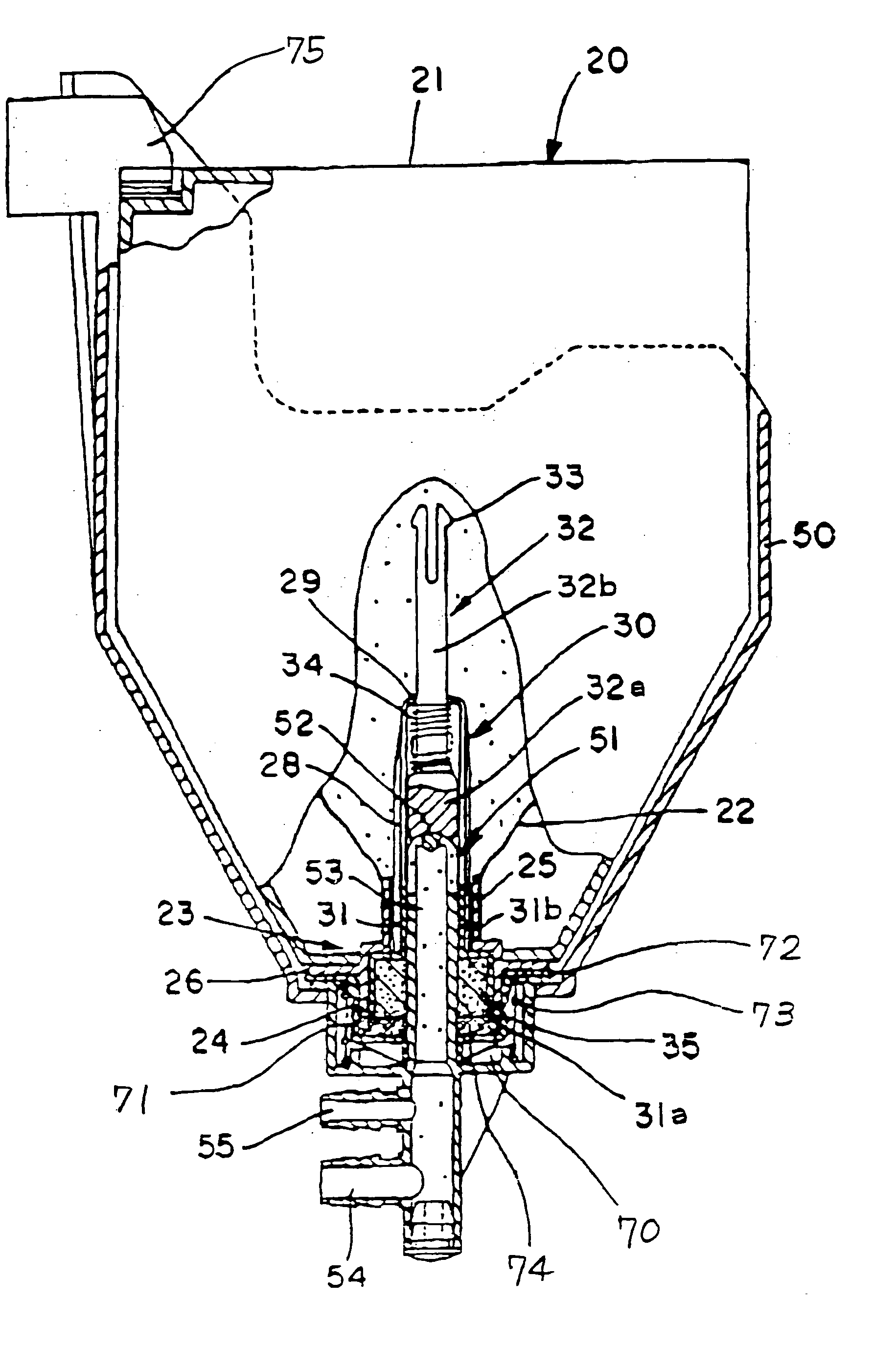
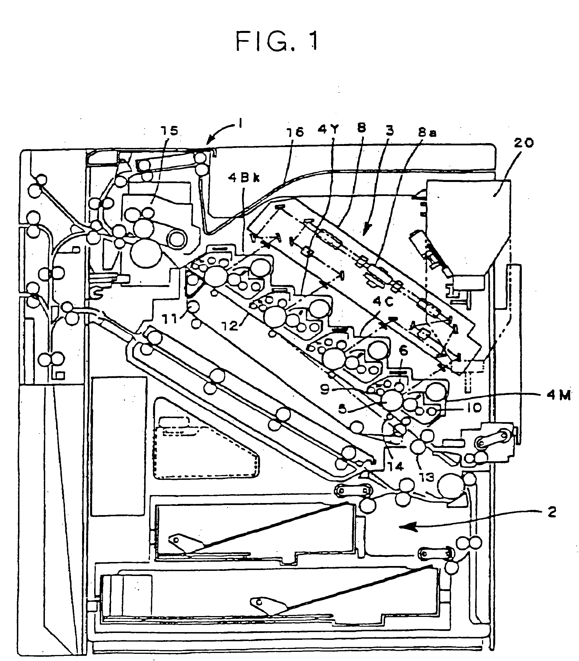
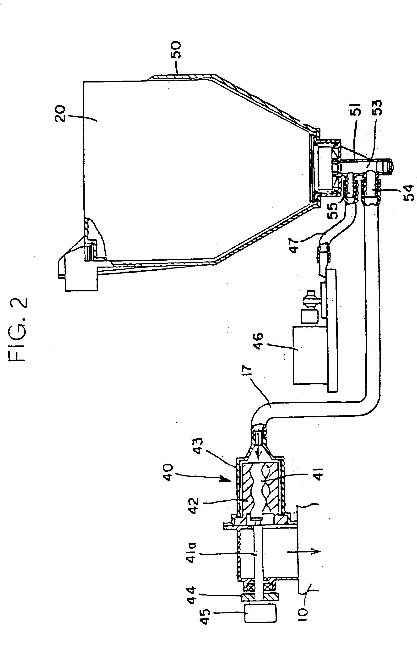
[0027] Referring to FIG. 1 of the drawings, an image forming apparatus embodying the present invention is shown and implemented as a color laser printer by way of example. As shown, the printer includes a printer body 1. A sheet feeding section and an image forming section 3 are respectively arranged in the upper portion and lower portion of the printer body 1. The image forming section 3 includes an image transfer belt device generally inclined downward toward the sheet feeding section 2. The image transfer belt device includes a plurality of (four in the illustrative embodiment) rollers 11 and an endless, image transfer belt 12 passed over the rollers 11. A drive source, not shown, is drivably connected to one of the rollers 11 for driving the belt 12 counterclockwise, as indicated by an arrow in FIG. 1.

[0028] A magenta (M), a cyan (c), a yellow (Y) and a black (Bk) image forming unit 4M, 4C, 4Y and 4Bk, respectively, are sequentially arranged in this order, as named from the bot...


PUM


Abstract

A toner container of the present invention stores powdery toner to be replenished via a toner outlet thereof and includes a container body. A shutter device is positioned in the toner outlet for selectively opening or closing the toner outlet. The shutter device includes an opening / closing member, a resilient member constantly biasing the opening / closing member from the inside toward the outside of the container body, and a support member supporting the resilient member and opening / closing member. The toner container is simple and easy to mount and dismount from an image forming apparatus while surely preventing the toner from leaking.

Description

BACKGROUND OF THE INVENTION [0001] 1. Field of the Invention [0002] The present invention relates to a copier, printer, facsimile apparatus or similar electrophotographic image forming apparatus and more particularly to a toner container to be removably mounted to an image forming apparatus for replenishing toner to a developing device. [0003] 2. Description of the Background Art [0004] While a toner container mounted to an image forming apparatus is usually replaced by the user, the replacement often causes toner to scatter and is awkward to perform. A toner container easy to mount and dismount without causing toner to scatter has been proposed in various forms in the past. For example, a toner container whose cap is automatically opened when the container is moved and is therefore easy to use is available. However, this kind of toner container has sophisticated, expensive structure. [0005] There has been proposed an image forming apparatus and a toner container constructed to solv...

Claims


Application Information

Patent Timeline
IPC IPC(8): G03G15/08
CPCG03G2215/0682G03G2215/0692Y10S222/01G03G15/0874G03G15/0877G03G15/0886G03G15/0865G03G15/0855G03G15/0879
Inventor SUDO, KAZUHISAHATTORI, YOSHIO
Owner RICOH KK
Learn More