

Device for controlling clearance in a gas turbine
- Summary
- Abstract
- Description
- Claims
- Application Information
AI Technical Summary
Benefits of technology
Problems solved by technology
Method used
Image

Examples
Embodiment Construction
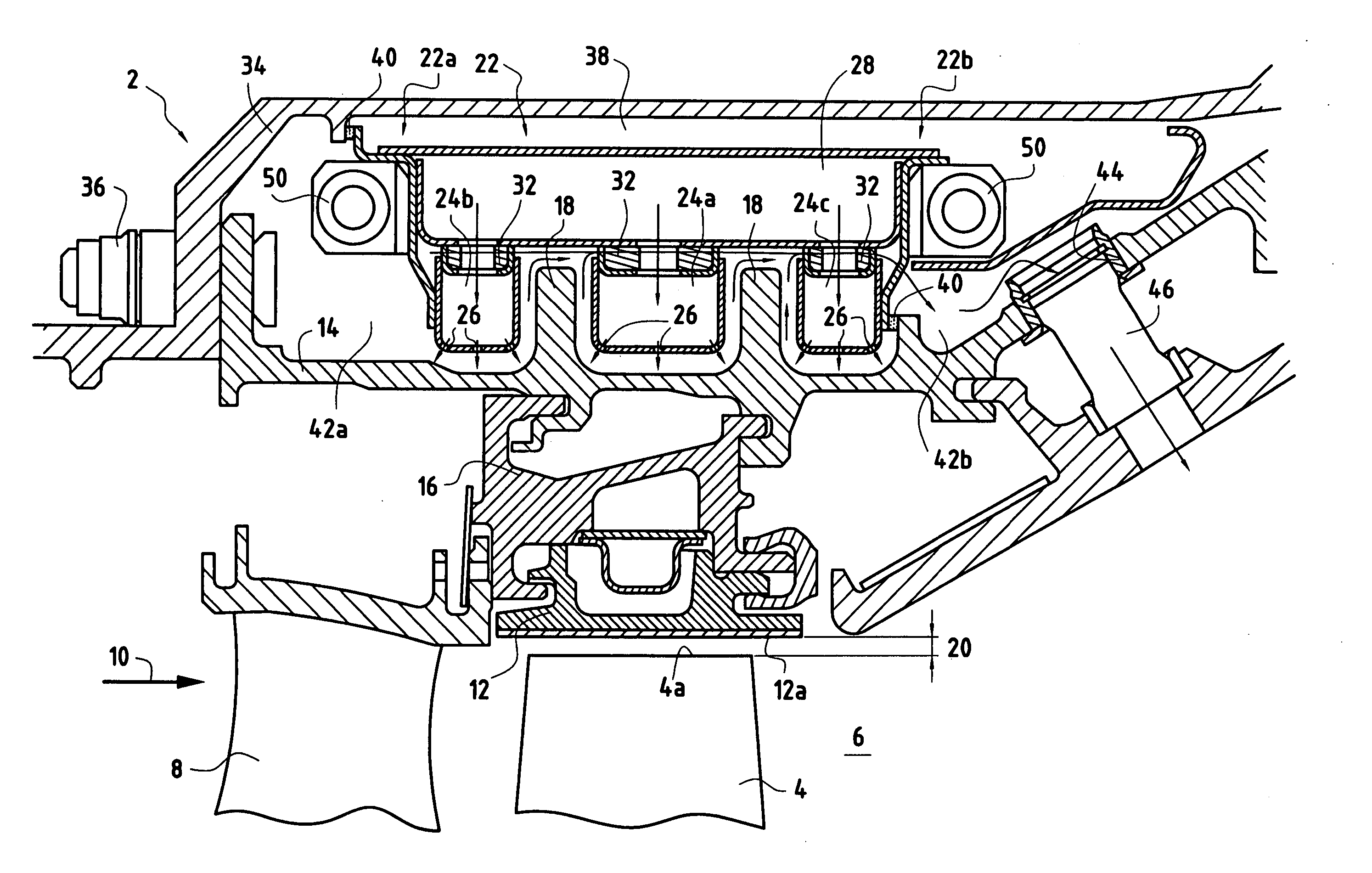
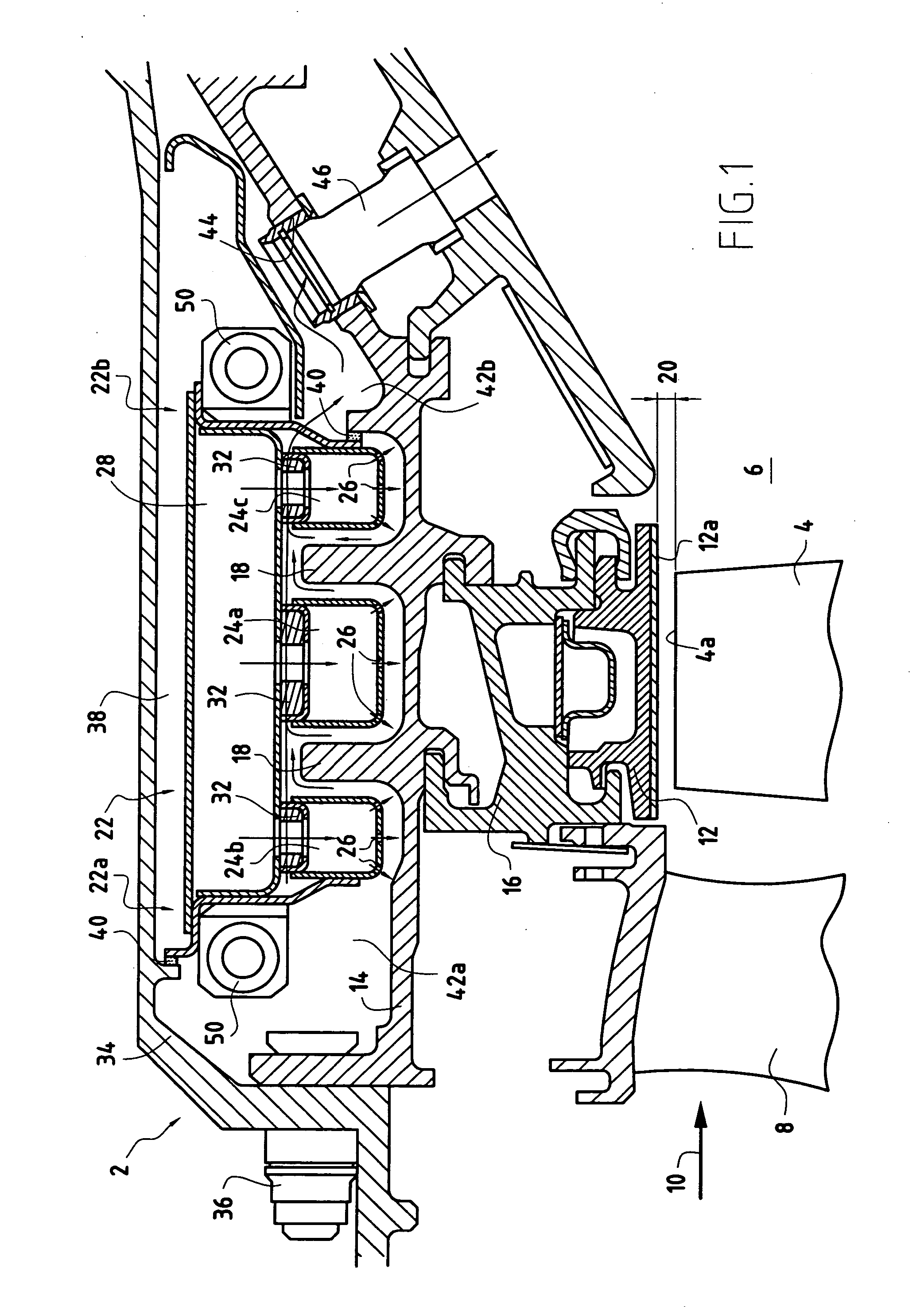
[0018]FIG. 1 is a longitudinal section view of a high-pressure turbine 2 of a turbomachine fitted with a clearance control device of the invention. Nevertheless, the present invention could equally be applied to a low-pressure turbine of a turbomachine or to any other type of machine fitted with a clearance control device.
[0019] The high-pressure turbine 2 is made up in particular of a plurality of moving blades 4 disposed in a flow passage 6 for hot gas coming from a combustion chamber (not shown) of the turbomachine. These moving blades 4 are disposed downstream from stationary vanes 8 of the turbine in the flow direction 10 of the hot gas in the passage 6.
[0020] The moving blades 4 of the high-pressure turbine 2 are surrounded by a plurality of stationary ring segments 12 disposed circumferentially around the axis of the turbine so as to form a surface that is circular and continuous. These ring segments 12 are mounted on an inner casing 14 of the turbomachine via a plurality o...
PUM
 Abstract
Description
Claims
Application Information