Electrical connection device with protected contact

Inactive Publication Date: 2005-02-24
ENTRELEC
View PDF8 Cites 6 Cited by
  • Summary
  • Abstract
  • Description
  • Claims
  • Application Information

AI Technical Summary

Benefits of technology

[0009] It is an object of the present invention to remedy the abovementioned drawbacks by providing a connection device whose design rules out

Problems solved by technology

Although such devices are perfectly satisfactory in terms of the electrical connection between the conductors and the contact plates, the insertion of the conducting element into the housing undern

Method used


Image

  • Electrical connection device with protected contact
  • Electrical connection device with protected contact
  • Electrical connection device with protected contact

Examples


first embodiment

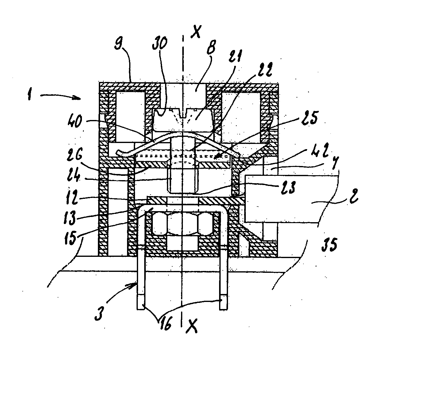
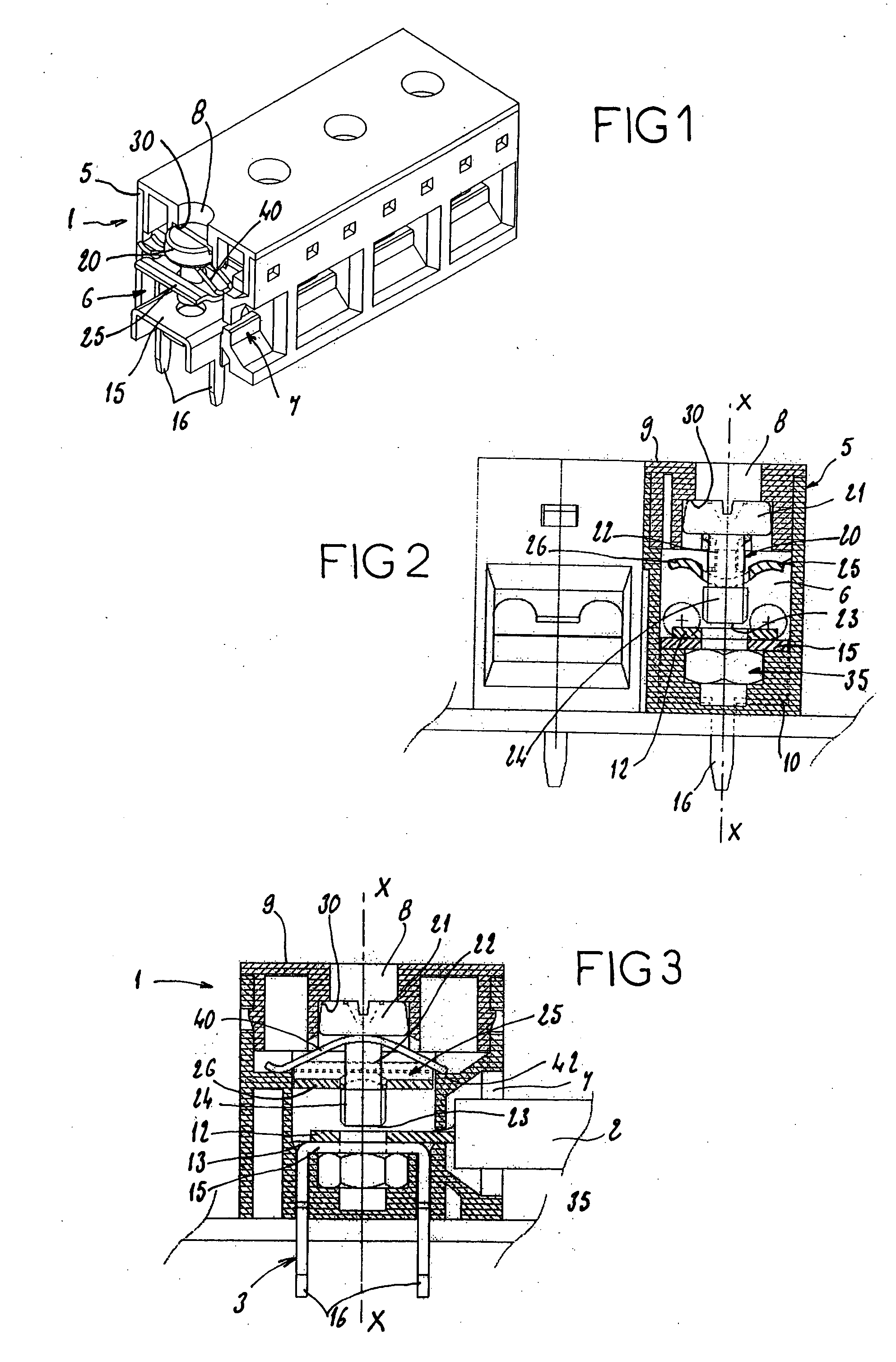
[0032] The electrical connection device 1 according to the invention shown in FIGS. 1 to 3 is for connecting a conducting element 2 external to the device, to an electrical contact plate 3 belonging to this device.

[0033] The connection device described below can of course be understood as a connection terminal or a socket panel and the conducting element may be either a conducting cable with a stripped end, or a conducting ring terminal.

[0034] The electrical contact plate 3 may for example be embedded in an electronic board or in any other electrical system.

[0035] The connection device 1 comprises a case 5 which is made of an electrically insulating material and defines at least one housing 6. This electrically insulating case forms a virtually closed envelope vis-à-vis the external environment and comprises a connection opening 7 designed to allow the electrically conducting element 2 to be inserted into the housing 6 from the exterior of the device, and a work opening 8 for the ...

second embodiment

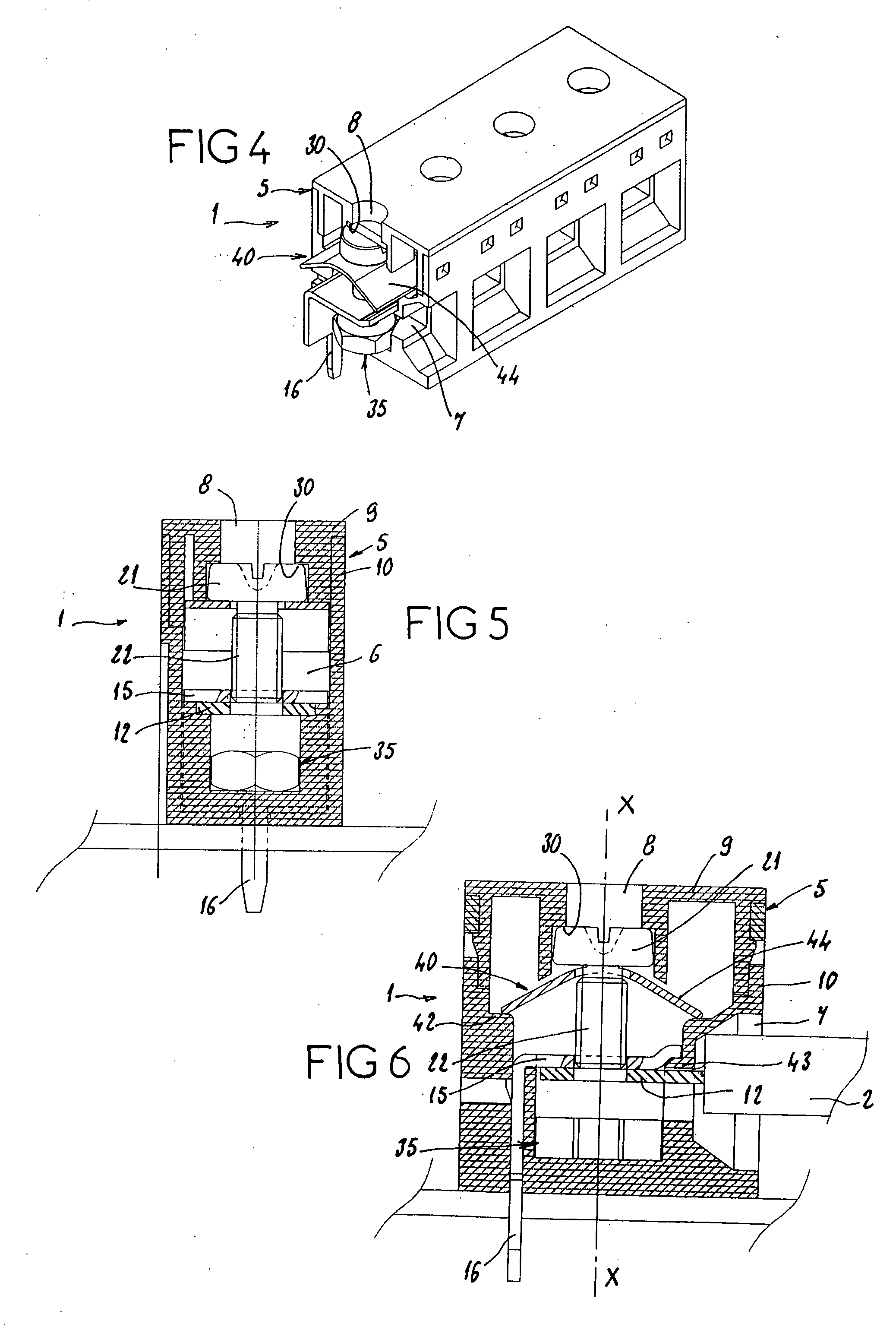
[0051] In the second embodiment shown in FIGS. 4 to 6, the clamping means 25 take the form of an internally threaded hole formed in the ring terminal 12 of the conducting element 2. The same reference numbers denote components identical or similar to the previous embodiment. The elastic restoring means 40 take the form of a thin element 44 which is also pressed against the flats 42 projecting from the walls 5 of the case as in the previous embodiment.

[0052] This second embodiment differs from the first embodiment in that the web 15 of the contact plate 3 is in contact with a flat 43 on one of the walls of the case 5 in the vicinity of the connection opening 7. The ring terminal 12 of the conducting element 2 is inserted into the opening 7 and laid against the web 15 of the plate 3, on the underside of the latter and bearing against the edge of the opening 7 from which the flat 43 projects.

[0053] Thus, after having put the conducting element 2 in position inside the housing 6, the s...

fourth embodiment

[0058] In the fourth embodiment shown in FIGS. 10 to 12, the shank 22 and the head 21 are of the same diameter. The clamping means 25 are represented in by the free end 23 of the screw 20. Thus, after inserting the ring terminal 12 of the conducting element 2 into the housing 6 for it to contact the web 15 of the plate 3, the screw 20 is simply screwed through the nut means 35 to bring the free end 23 against the ring terminal 12 and sandwich it between it and the web 15 of the plate 3.

[0059] As shown more particularly in FIG. 10, the nut means 35 are carried by walls 53 which are part of the same mass of material as the web 15 of the plate 3 and extend in the direction of the work opening 8, inside the housing 6. The nut means 35 take the form of an internally threaded thin element 54 extending transversely with respect to the screw 20.

[0060] Also, the connection opening 7 is closed by a hinged flap 55 supported by one of the walls of the case 5 and illustrated in the open and clo...


PUM


Abstract

This is a connection device comprising an insulating case and it defines at least one housing and various connection openings and work openings, an electrical contact plate, a screw mounted in the housing, and clamping means stressed by the screw in order when required to immobilize together the conducting element and the contact plate. The case comprises means for retaining the screw inside the housing so that only the head of the screw is accessible from the outside through the work opening, the clamping means being completely insulated from the outside by the case, and rotation of the screw moves the clamping means translationally inside the housing between two separate positions at a distance from each other.

Description

BACKGROUND OF THE INVENTION [0001] The present invention relates to electrical connection devices particularly for allowing electrical connection between a contact plate belonging to the device and an electrical element external to this device. DESCRIPTION OF THE PRIOR ART [0002] The devices usually met with are the type comprising: [0003] a case made of an electrically insulating material which defines at least one housing and which has at least one connection opening for the insertion into the housing of an electrically conducting element from outside of the device, and at least one work opening for the passage of a work tool, [0004] at least one electrical contact plate comprising at least one web situated in the housing and at least one leg projecting out of the case, [0005] at least one screw comprising a threaded shank and a driving head, which screw is mounted movably inside the housing so as to be turned by the tool, and [0006] clamping means which are mounted in the housing...

Claims


Application Information

Patent Timeline
IPC IPC(8): H01R4/34H01R4/38H01R9/24H01R12/55
CPCH01R12/515H01R4/38
Inventor CISEY, JOHANN
Owner ENTRELEC
Why Eureka
Try Eureka