
Image detecting apparatus, image detecting method, and image detecting program

a technology of image detection and image, applied in the direction of electronic editing digitised analogue information signals, instruments, television systems, etc., can solve the problems of trouble and time, user cannot specify an image in a specifiable unit, and cannot be accurately and easily specified, so as to achieve detection quickly, accurately and easily

Inactive Publication Date: 2005-02-24
SONY CORP
View PDF7 Cites 123 Cited by
  • Summary
  • Abstract
  • Description
  • Claims
  • Application Information

AI Technical Summary

Benefits of technology

[0014] The specifying means then specifies a target frame image from the plurality of frame images displayed by the display controlling means. Thus, edit points such as a start point and an end point of a target scene and the like can be detected quickly, accurately, and easily from the plurality of frame images forming the moving image.
[0019] Thus, edit points such as a start point and an end point of a target scene and the like can be detected quickly, accurately, and easily from the plurality of frame images forming the moving image.

Problems solved by technology

Therefore, the user may miss a scene in which a target edit point is present while checking the positions of the operating keys on the remote control, or the user may erroneously operate the remote control while checking the reproduced image.
In addition, when searching for an edit point, the user cannot specify an image in a specifiable unit, for example, a frame unit.
Therefore, a target edit point cannot be specified accurately and easily, so that trouble and time may be required before specifying the target edit point.
Furthermore, while editing operations on the recorded data are enabled after changing to the edit mode, as described above, some users may not know the operation for changing to the edit mode and thus take time before editing the recorded data.
When setting an edit point in a program recorded for a long time, for example, it takes a considerable time to find the edit point by reproducing the program from the start.

Method used


Image

  • Image detecting apparatus, image detecting method, and image detecting program
  • Image detecting apparatus, image detecting method, and image detecting program
  • Image detecting apparatus, image detecting method, and image detecting program

Examples


first example

[0235] A description will hereinafter be made of a few concrete examples of the recording and reproducing apparatus 600 according to the second embodiment that makes it possible to quickly detect an image of a target scene using a moving image display. FIG. 14 is a diagram of assistance in explaining a first example of the recording and reproducing apparatus 600 that makes it possible to quickly detect a target scene using a moving image display.

[0236] As shown in FIG. 14, a CPU 40 of the recording and reproducing apparatus 600 in this example can provide a first moving image display area 201M1, a second moving image display area 201M2, and a third moving image display area 201M3. The CPU 40 controls a buffer control circuit 17 to start reading image data from three points: a head point of a target title (one information signal set of a broadcast program or the like), a point ahead of the head point by 10 seconds in reproduction time, and a point ahead of the head point by 20 secon...

second example

[0255] The foregoing first example provides reading start points (reproducing points) at predetermined intervals to thereby prevent an image of a target scene from being missed and to realize quick detection of the image of the target scene. The second example makes it possible to quickly and easily detect an image of a target scene as an edit candidate point from image data recorded for a long period of time, for example.

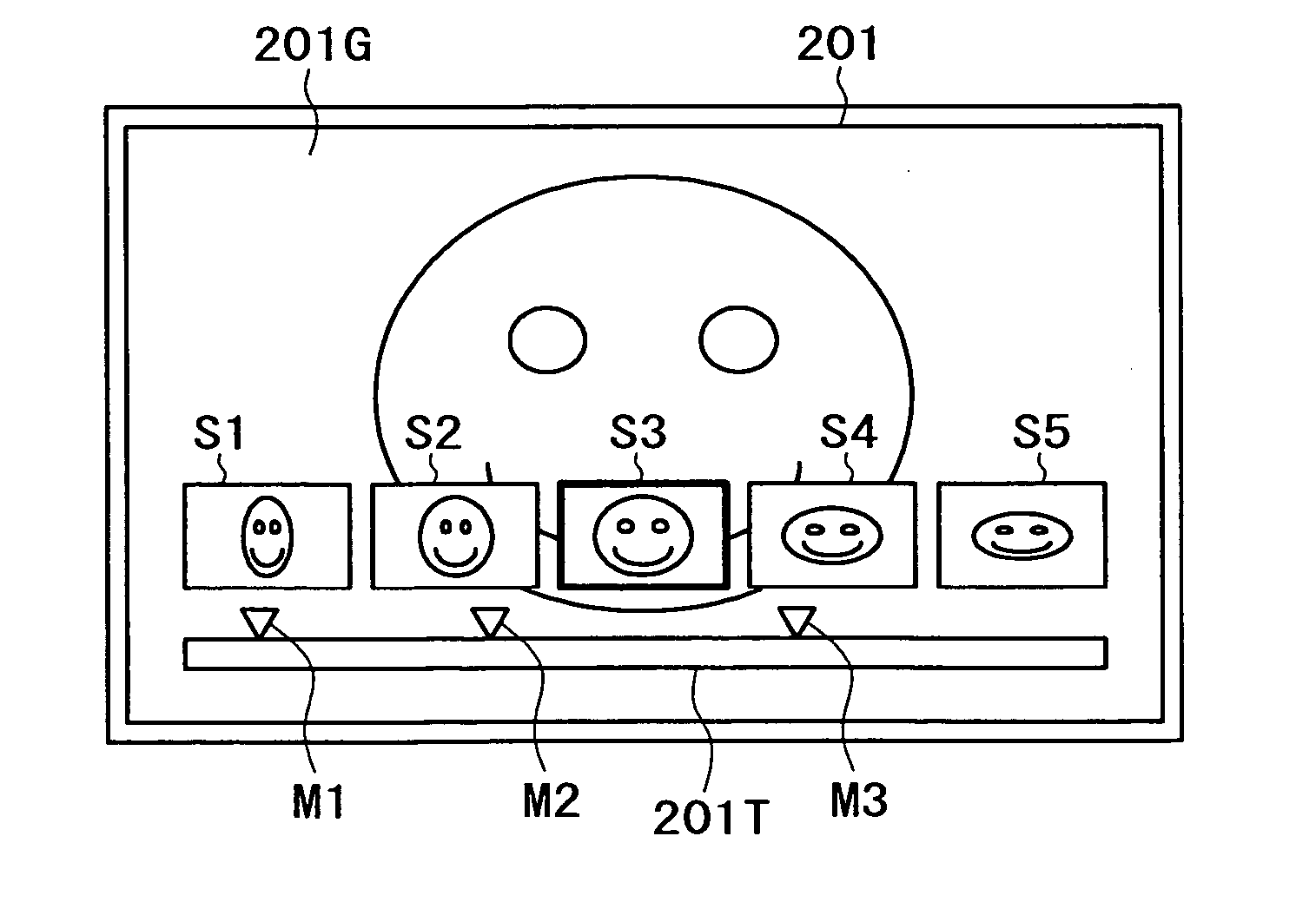
[0256]FIG. 15 is a diagram of assistance in explaining an example of an image displayed on the display screen 201 of the monitor receiver by a recording and reproducing apparatus 600 in the second example of the second embodiment. When a title to be reproduced is selected from among titles (information signal sets of broadcast programs or the like) recorded on a recording medium 18, a CPU 40 of the recording and reproducing apparatus 600 first provides a main image display area 201M and displays a time line 201T corresponding to the total amount of image data of t...

third example

[0367] Instead of the user setting the number and position of reproducing points as in the foregoing second example, a recording and reproducing apparatus in the third example effects automatic control to change the number and position of reproducing points according to image reproduction speed, thereby making it possible to quickly and accurately detect a target image of a target scene from a series of titles. Incidentally, the recording and reproducing apparatus in the third example is the same as the recording and reproducing apparatus 600 shown in FIG. 13.

[0368] The recording and reproducing apparatus 600 in the third example allows free setting of speed of title reproduction at the time of title reproduction. The reproduction speed can be set via the remote control 150. At the time of reproduction, a reproduced image is displayed on the entire surface of the display screen 201, as shown in FIG. 30. At the same time, a sub-image display area SG1 is provided in a lower portion o...


PUM

PropertyMeasurementUnit
timeaaaaaaaaaa
timeaaaaaaaaaa
display speedaaaaaaaaaa

Abstract

An image detecting apparatus has an edit function with good operability and compatibility. When a chapter mark key on a remote control is pressed while an image reproducing system including an MPEG video decoder, a video signal post-processing circuit, a combining circuit, and an NTSC encoder is reproducing image data recorded on a recording medium, a CPU obtains information for identifying the image being reproduced and displayed, and then records the information on the recording medium. With reference to the image provided with a chapter mark, a still image generating circuit displays reduced still images, for example, so that a target image can be specified. Reproduction and editing can be performed with reference to the specified image.

Description

BACKGROUND OF THE INVENTION [0001] The present invention relates to an image detecting apparatus included in a digital recorder, for example, for detecting a target image from image information recorded on a recording medium, an image detecting method and an image detecting program applied to the image detecting apparatus. [0002] Some existing digital recorders for home use include an edit function. When a digital recorder for home use including an edit function performs an editing operation, such as deleting an unnecessary scene or extracting only a necessary scene from a recorded television program, for example, the editing operation is performed by changing the digital recorder to an edit mode. [0003] Specifically, a user of the digital recorder for home use first changes the digital recorder to the edit mode, and then reproduces the recorded television program to be edited. While checking the reproduced image, the user searches for an edit point of a target scene by operating a ...

Claims


Application Information

Patent Timeline
Patent Type & Authority Applications(United States)
IPC IPC(8): G11B20/10H04N5/76G11B27/00G11B27/034G11B27/10G11B27/32G11B27/34G11B27/36H04N5/91H04N5/93
CPCG11B27/034G11B27/105G11B27/329G11B27/34G11B2220/61G11B2220/20G11B2220/2516G11B2220/2525G11B27/36G11B20/10G11B5/76G11B27/10
Inventor YAMAGAMI, RUITAKAHASHI, YOKODATE, OSAMU
Owner SONY CORP
Learn More