Elastomeric material application systems and methods

a technology of elastomeric materials and applications, applied in the field of fabric application systems and methods, can solve the problems of unique challenges to furniture makers, lack of substantial support, and difficulty in prior art methods and structures

Active Publication Date: 2005-03-03
CVEK SAVA
View PDF6 Cites 7 Cited by
  • Summary
  • Abstract
  • Description
  • Claims
  • Application Information

AI Technical Summary

Benefits of technology

[0018] The framework can have a groove therein and a locking spline can be received into the groove with a portion of the panel of material disposed therebetween thereby to secure the panel of material relative to the framework. In such a case, the means for inducing an attachment of the panel of material to the frame member can comprise a means for pressing the locking spline into the groove. That means could in one embodiment comprise a pressing arrangement with a tooth member and a means for reciprocatably driving the tooth member. There can additionally be a means, such as a rail contoured to match a contour of the framework, for enabling the tooth member to travel along an edge of the framework to enable a progressive pressing of the locking spline into the groove.

Problems solved by technology

As such, the “A” layer itself need only be attached to the frame structure; it need not provide substantial support.
Attempting that that secure attachment presents unique challenges to the furniture maker.
Prior art methods and structures have struggled in seeking to confront the aforementioned and further challenges of applying a fabric panel to a framework.
Many attachment methods and systems have proven to be undesirably inefficient.
Other methods and arrangements have failed to provide adequate retention of the fabric panel.
Still further, particularly since the fabric panel acts as the sole means of support to furniture occupants and the like, it has been found that many prior art attachment arrangements have left the fabric panel and the edges thereof disadvantageously vulnerable to dislodging, damage, and tampering.
Also, many prior art structures and methods are unable to adapt to varied framework structures.
These and further disadvantages have heretofore prevented elastomeric material application methods and arrangements from achieving widespread use and commercial success.

Method used


Image

  • Elastomeric material application systems and methods
  • Elastomeric material application systems and methods
  • Elastomeric material application systems and methods

Examples


Embodiment Construction

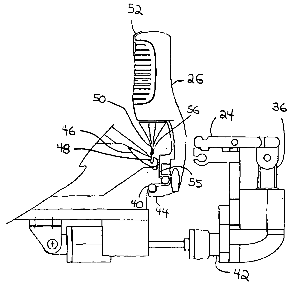
[0043] The elastomeric material application systems and methods disclosed herein are subject to a wide variety of embodiments. However, to ensure that one skilled in the art will be able to understand and, in appropriate cases, practice the present invention, certain preferred embodiments of the broader invention revealed herein are described below and shown in the accompanying drawing figures. Before any particular embodiment of the invention is explained in detail, it must be made clear that the following details of construction, descriptions of geometry, and illustrations of inventive concepts are mere examples of the many possible manifestations of the invention.

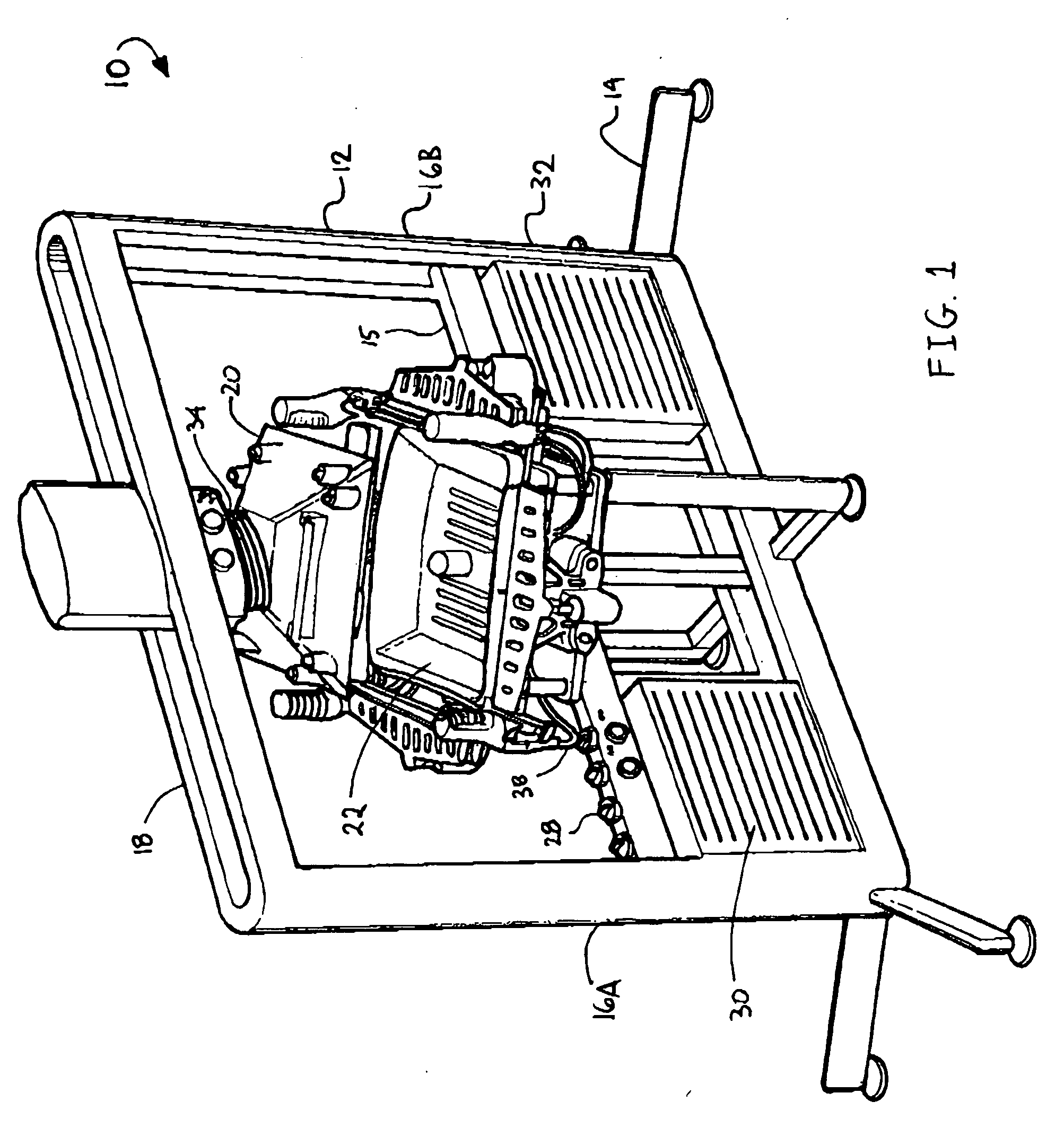
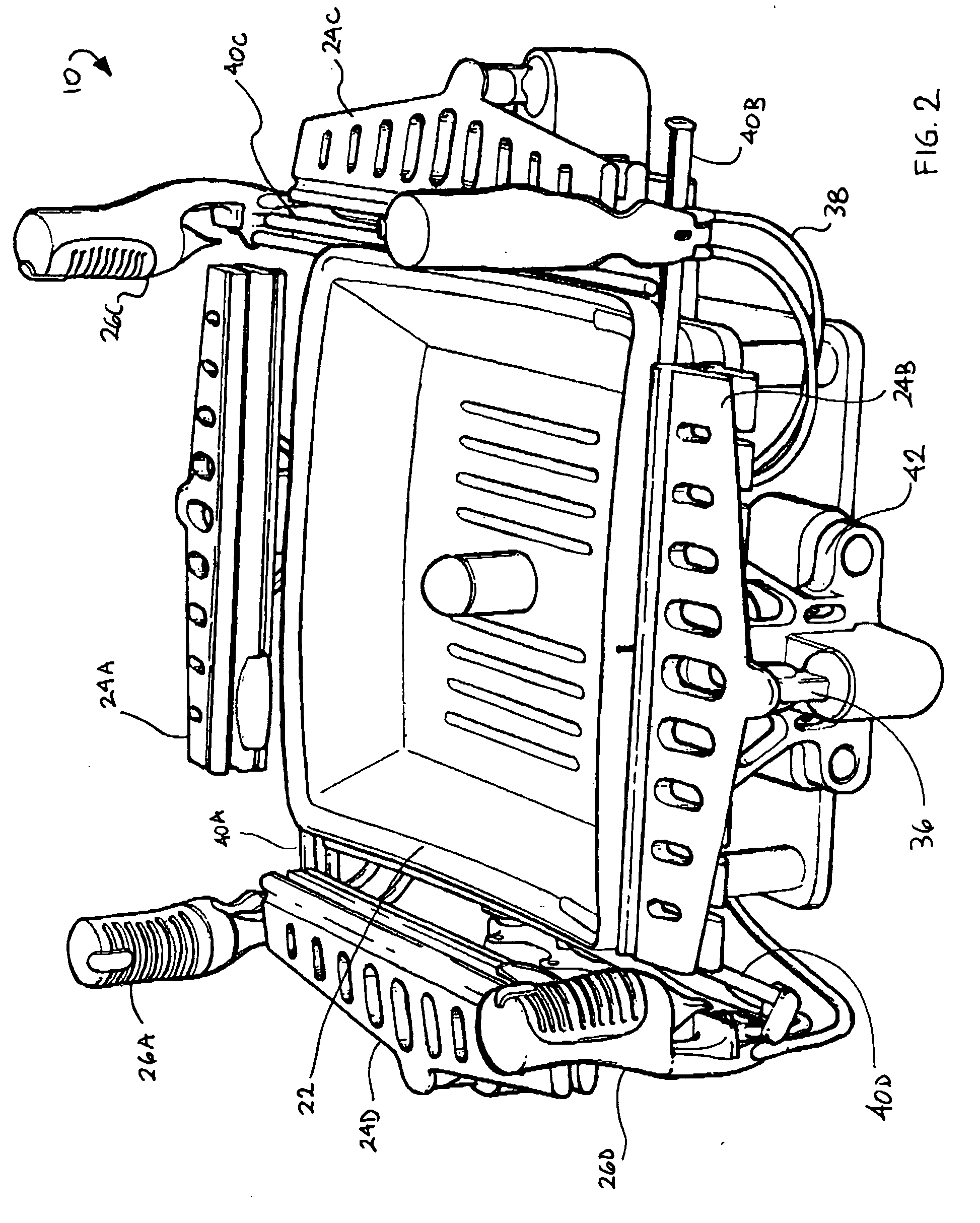
[0044] Looking more particularly to the drawings, an embodiment of an elastomeric material application system according to the present invention is indicated generally at 10 in FIGS. 1 through 3. The elastomeric material application system 10 has a rectangular frame 12 that is supported by a plurality of legs 14. The fr...


PUM

PropertyMeasurementUnit
heightaaaaaaaaaa
forceaaaaaaaaaa
sizeaaaaaaaaaa

Abstract

A material application system for applying a panel of material to a framework with a shoe for retaining the framework, a nest, opposed mechanisms for retaining opposite portions of the panel of material traversing between the shoe and the nest, an arrangement for selectively moving the shoe and the nest into and out of an engaged position wherein the panel of material is sandwiched between the shoe and the nest and a disengaged position, and an arrangement for inducing an attachment of the panel of material to the framework. The opposed mechanisms can be clamping mechanisms, which can be segmented and individually moveable to enable variable pretensioning. A contoured deflection control member can alternatively produce variable pretensioning. A pressing arrangement with a tooth member can press a locking spline into a groove in the framework to secure the material.

Description

FIELD OF THE INVENTION [0001] The present invention relates generally to fabric application systems and methods. More particularly, disclosed and protected herein are systems and methods for the application of elastomeric materials. BACKGROUND OF THE INVENTION [0002] In traditional upholstered furniture construction, a layer of fabric, commonly referred to as any “A” layer, is retained relative to a frame structure overlying one or more subsurface layers, commonly referred to as “B”, “C”, and possibly further layers. The subsurface layers, which can comprise additional fabric layers, foam layers, springs, bands, and the like, generally provide continuous support to the “A” layer. As such, the “A” layer itself need only be attached to the frame structure; it need not provide substantial support. With this, attachment methods for “A” layers in such structures commonly involve simple stapling, adhering, or the like. [0003] More recently, furniture constructions have been developed wher...

Claims


Application Information

Patent Timeline
Patent Type & Authority Applications(United States)
IPC IPC(8): B21D39/00B23P11/02B23P19/00B23Q3/00B23Q7/00B25B27/14B68G7/00B68G7/05B68G15/00
CPCB29C65/56Y10T29/49998B29C66/534B29C66/69B29C66/8322B29L2012/00B29L2031/443B29L2031/737B68G7/05B68G15/005Y10T29/53Y10T29/49895Y10T29/488Y10T29/489Y10T29/49874Y10T29/53961Y10T29/49867Y10T29/53974Y10T29/486B29C65/565B29C66/12461B29C66/71
Inventor CVEK, SAVA
Owner CVEK SAVA
Why Eureka
Try Eureka