Riding mower

a construction and riding mower technology, applied in the field of riding mowers, can solve the problems of having to get off the vehicle body, hinder the right-and-left balance of the body, and hinder the straight traveling, so as to achieve the effect of reducing the number of components, facilitating straight traveling performance of the body, and simplifying the construction around the brake operating portion

Active Publication Date: 2005-03-03
ISEKI & CO LTD
View PDF9 Cites 41 Cited by
  • Summary
  • Abstract
  • Description
  • Claims
  • Application Information

AI Technical Summary

Benefits of technology

[0007] It is an object of the present invention to make braking and parking operations of the body simple, and moreover, to improve the operation of the traveling body compared to the prior art by an improved right-and-left weight balance of the body, and to improve operations at the mower deck side, in particular, operations related to the mowing height adjustment compared to the prior art.
[0013] According to the first aspect of the present invention, since the brake pedal 69 for braking the right and left rear wheels 3 and 3 and the parking operation member 78 for maintaining a step-on condition of the brake pedal 69 are provided on the step 67, a step-on condition of the brake pedal 69 can be maintained by, for example, stepping on the parking operation member 78 with the left foot after applying a step-on brake of the brake pedal 69 with the right foot, thus the body can be stopped without using hands whereby the stopped condition can be maintained over an extended period of time.
[0014] According to the second aspect of the present invention, since the brake pedal 69 can be supported so as to allow a step-on operation by utilizing the lift shaft 53 to elevate the mower 43, construction around the brake operating portion is simplified, no extra shaft to support the brake pedal 69 is required, and the number of components is also reduced, and the whole mower can be constructed at a reasonable price.
[0015] According to the third aspect of the present invention, since the pair of variable capacity pumps 25 and 25 are provided in a front and back direction, and on the side thereof, the PTO shaft 42 is also provided in a manner maintaining a parallel condition, therefore, compared to a case where the variable capacity pumps 25 and 25 are provided in a row in the right and left direction, the breadth of the body does not become wide, thus the body can be constructed with a compact size.
[0016] According to the fourth aspect of in present invention, since the PTO shaft 42 is off-center to one side with respect to the center in the right and left direction of the body, even the mower 43 whose discharge port side is heavy can be balanced right and left when being hoisted, and straight traveling performance of the body can be kept satisfactory.
[0017] In addition, according to the fifth aspect of the present invention, since the adjuster 190 on the link arm 51 side can be remotely operated by the setter 175a of the operator's seat 28 side, an operator can change a mowing height of the mower 43 while remaining seated on the operator's seat 28, and avoid the trouble of having to get off the vehicle body as described above, and operation of the riding mower can be improved.

Problems solved by technology

However, this PTO shaft exists at the center in the right and left direction of the body, and in particular, when a mower deck of a three cutting blade-type is mounted, the right-and-left-balance of the body is hindered since the exhaust side is heavy.
In addition, the body may be inclined toward the exhaust side, which hinders straight traveling even when a straight advance of the body is intended.
However, when changing the mowing height, the trouble of having to get off of the vehicle body each time for a change and perform a change operation of a height adjuster has been necessary.

Method used


Image

  • Riding mower
  • Riding mower
  • Riding mower

Examples


embodiment 1

[0036] Embodiment 1

[0037] Hereinafter, an embodiment of the present invention will be described based on the drawings.

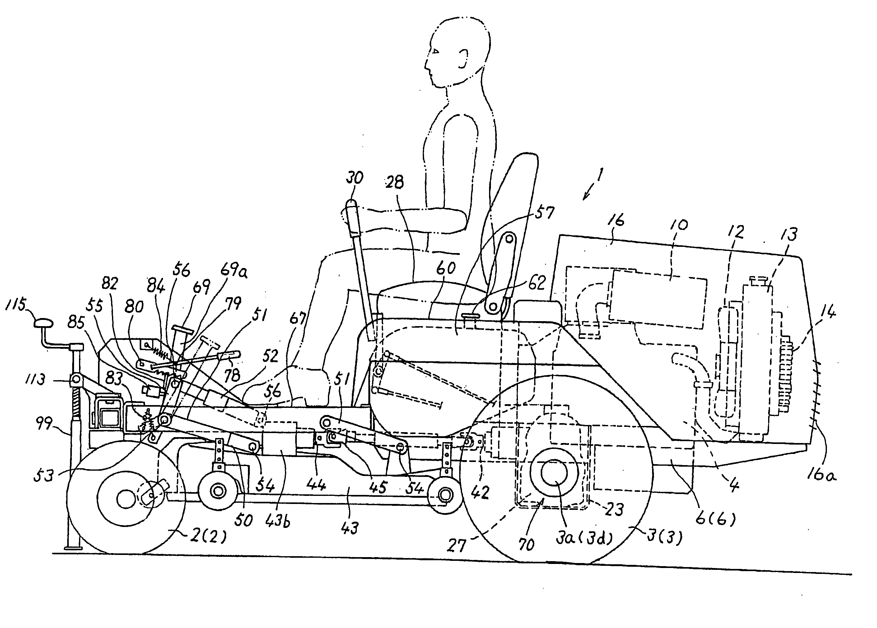
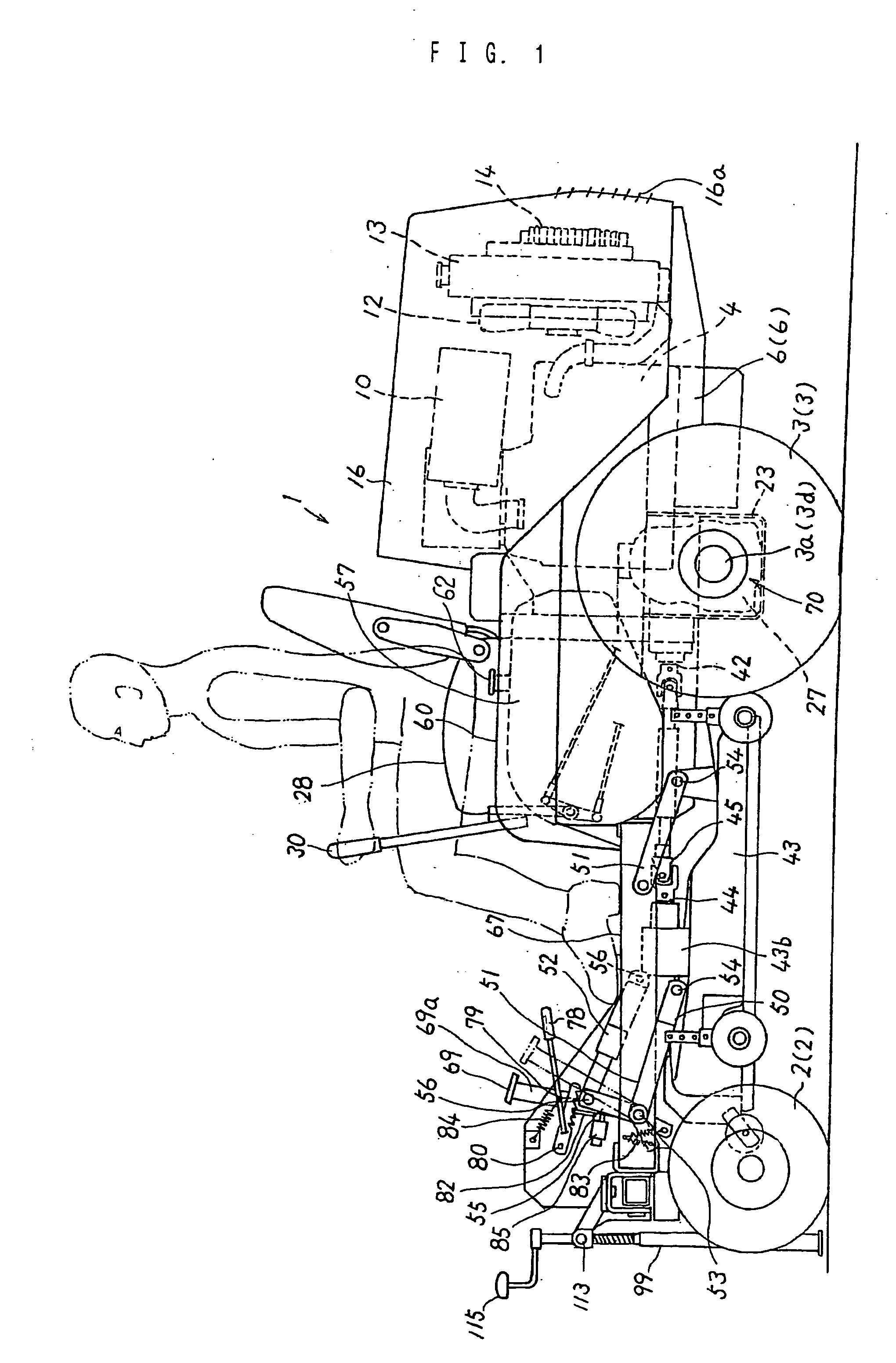
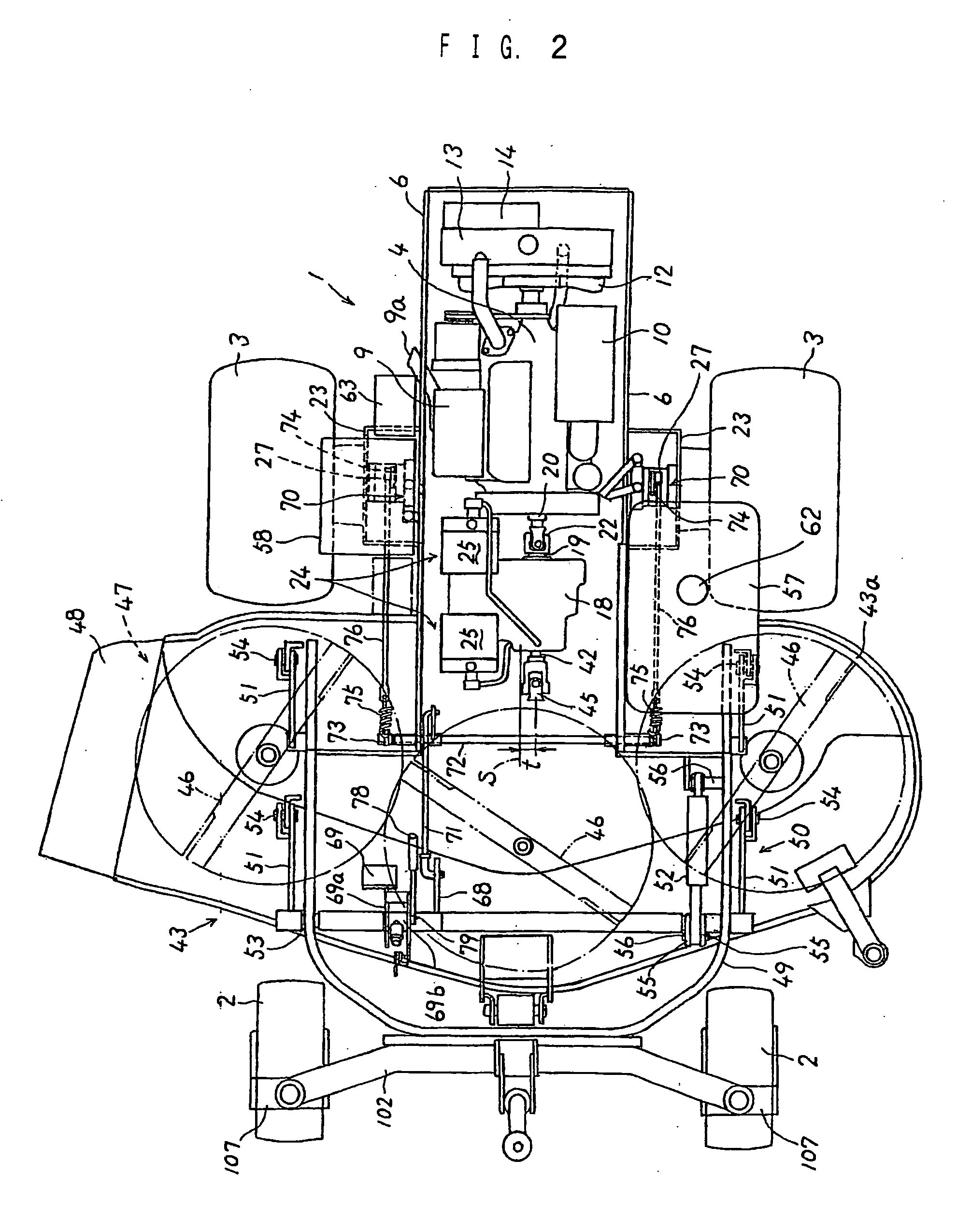
[0038] First, as a description of the construction, a riding-type lawn mower 1 is provided with front wheels 2 and 2 and rear wheels 3 and 3; the front wheels 2 and 2 are composed of non-driven-type caster wheels, and the rear wheels 3 and 3 are driven by the power of engine 4.

[0039] The engine 4 is provided at a rear part of the body, and is elastically supported via four vibration isolators (illustration omitted) between a pair of right and left main frames 6 and 6 provided along the anteroposterior direction.

[0040] The engine 4 is positioned more rearward than axles 3a and 3a of the rear wheels 3 and 3 in a view from the lateral side, and above the same, a muffler 9 and an air cleaner 10 are disposed. A tail pipe 9a of the muffler 9 is provided in a downwardly extending manner from a main-body portion and orients its exhaust opening portion laterally outward.

[...


PUM


Abstract

As an embodiment of the present invention, a brake pedal 69 for braking right and left rear wheels 3 and a parking operation member 78 for maintaining a step-on condition of the brake pedal 69 are provided on a step 67. As a result, the step-on condition of the brake pedal 69 can be maintained by, for example, stepping on the parking operation member 78 with the left foot after applying the step-on brake of the brake pedal 69 with the right foot. Thus the body can be stopped without using hands and the stopped condition can be maintained over an extended period of time. Braking and parking operations of the body are simple, and moreover, an improved right-and-left weight balance of the body improves the traveling body in operation, and operations at the mower deck side. In particular, operation related to mowing height adjustment can be improved.

Description

BACKGROUND OF THE INVENTION [0001] 1. Field of the Invention [0002] The present invention relates to a construction of a riding mower comprising caster-type right and left front wheels and driven-type right and left rear wheels, wherein a mower deck is mounted between the front and rear wheels so as to be capable of being lifted up and down. [0003] 2. Description of the Related Art [0004] A riding mower having right and left independent hydrostatic transmissions (HSTs), capable of operating a pair of right and left steering levers in the back-and-forth direction to individually actuate these hydrostatic transmissions (HSTs) to advance or retract the body or reversing one to perform an on-the-spot ground turn is known in the art. [0005] In such a riding mower, a brake pedal to stop the body and a brake operation member for parking are provided at separate positions. For a parking operation, an operator must perform a parking operation while letting go of the steering levers. In addit...

Claims


Application Information

Patent Timeline
Patent Type & Authority Applications(United States)
IPC IPC(8): A01D34/64A01D34/66A01D34/74
CPCA01D69/10A01D34/74A01D34/64A01D34/661
Inventor GOTO, RENSHIOKAMOTO, SUGURUAKAMATSU, KATSUTOSHI
Owner ISEKI & CO LTD
Why Eureka
Try Eureka