Condenser

a condenser and condenser technology, applied in the field of condensers, can solve the problems of deteriorating performance, affecting the performance of the condenser, and affecting the efficiency of the condenser, so as to reduce the electric power consumption of the condenser, and improve the performance of the condenser

Inactive Publication Date: 2005-03-03
LG ELECTRONICS INC
View PDF4 Cites 29 Cited by
  • Summary
  • Abstract
  • Description
  • Claims
  • Application Information

AI Technical Summary

Benefits of technology

[0032] According to the invention, the refrigerant is outputted to the super-cooled liquid region through the combined refrigerant path, so that the two-phase region having good heat transmission is substantially increas

Problems solved by technology

Thus, the heat exchanger suffers more damage even when being the same size.
However, this approach has been limited to a certain extent.
C

Method used


Image

  • Condenser
  • Condenser
  • Condenser

Examples


Embodiment Construction

[0040] The following detailed description will present a condenser according to a preferred embodiment of the invention in reference to the accompanying drawings.

[0041]FIG. 3 is a block diagram schematically illustrating a structure including a condenser according to the present invention, FIGS. 4A and 4B show a state of a refrigerant in the condenser, and path and region through which the refrigerant passes, and FIG. 5 is graph and table showing relation between a super-cooled tube and a coefficient of performance.

[0042] To begin with, description will be made with reference to FIG. 3.

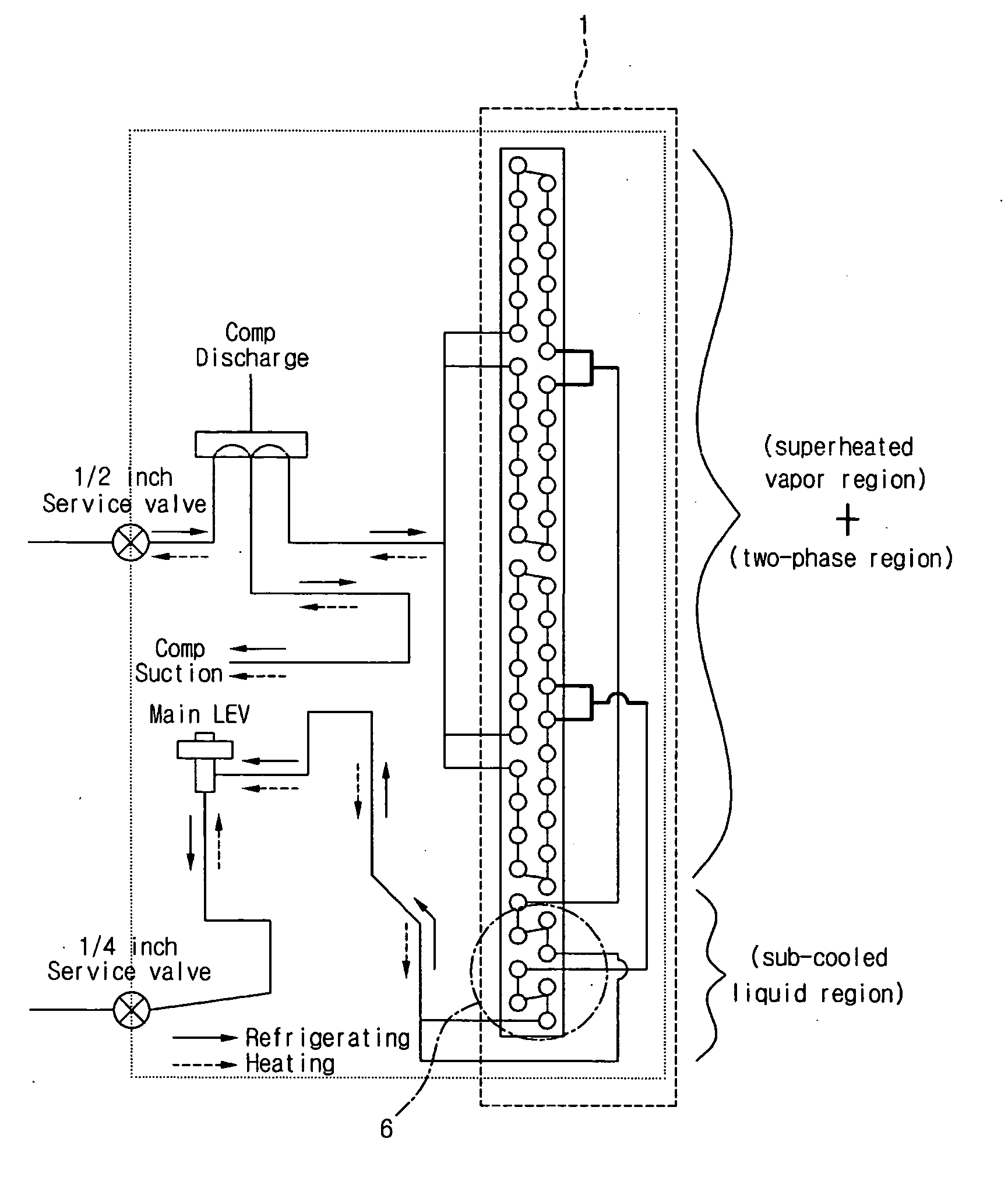
[0043] A refrigerant outputted from an indoor unit (not shown) is branched off into one or more paths through a service valve and a discharge valve of a compressor, and then inputted into a condenser 1.

[0044] The branched paths of the invention pass through tubes of super-heated vapor and two-phase regions and are combined into a tube of a super-cooled liquid region.

[0045] Further, the tube for t...


PUM


Abstract

A condenser where a refrigerant introduced from a compressor is coexisting in super-heated vapor, two-phase and super-cooled liquid states combines a plurality of refrigerant paths within at least one of super-heated vapor and two-phase regions to output the refrigerant to the super-cooled liquid region, and provides a proper percentage of the super-cooled liquid region.

Description

BACKGROUND OF THE INVENTION [0001] 1. Field of the Invention [0002] The present invention relates to a condenser, and more particularly to a condenser outputting a refrigerant to a super-cooled liquid region by combining a plurality of refrigerant paths on at least one of a super-heated vapor region and a two-phase region in the condenser where the refrigerant introduced from a compressor coexists in super-heated vapor, two-phase, and super-cooled liquid states, and providing a proper percentage of the super-cooled liquid region. [0003] 2. Background of the Related Art [0004] In general, a compression refrigerating cycle is completed by a compressor 5, a condenser 1, an expansion valve 3 and an evaporator 4. Currently, a stronger attention is drawn to a demand that consumption electric power should be lowered to the maximum level in air conditioners composed of the compression refrigerating cycle. [0005] Thus, various efforts have been propelled including improvement in performance ...

Claims


Application Information

Patent Timeline
IPC IPC(8): F25B39/04F25B40/02
CPCF25B40/02F25B39/04
Inventor HONG, KI SOOCHIN, SIM WONMOON, DONG SOO
Owner LG ELECTRONICS INC
Why Eureka
Try Eureka