Reinforced tension and compression reacting strut and method of making same

a technology of tension and compression and reacting struts, which is applied in the direction of girders, mechanical control devices, instruments, etc., can solve the problems of not being effective in reacting to compressive loads and vice versa, being limited in terms of reacting to a variety of force loads, and not being able to effectively absorb the load imposed on a portion of the vehicle. , to achieve the effect of effective reaction

Inactive Publication Date: 2005-03-03
KAISER COMPOSITEK
View PDF13 Cites 29 Cited by
  • Summary
  • Abstract
  • Description
  • Claims
  • Application Information

AI Technical Summary

Benefits of technology

[0011] It is, therefore, one of the primary objects of the present invention to provide a strut, formed of reinforced plastic composite material, and effective in reacting to both compressive and tension loads.

Problems solved by technology

While reinforced composites provide lighter weight and, in many cases, stronger reinforcement than that provided by the metal counterparts, they are limited in terms of reacting to a variety of force loads.
Thus, and while a reinforced composite strut is effective in reacting to tension loads, it may not be effective in reacting to compressive loads and vice versa.
These systems primarily absorb the shock of impact, but they do not effectively absorb the load imposed on a portion of the vehicle.
However, it is recognized that most struts are not effective in reacting to both tension loads and compression loads simultaneously.
This is due to the nature of the fibrous material and, particularly, the fact that it does not react well to a multitude of loads, simultaneously.
In tension, the strut could fail along its length.
However, since the load applied to the strut is not always pure tension, some shear loading could be imposed on the strut.
Moreover, composite materials are not capable of reacting effectively in shear and can fail.

Method used


Image

  • Reinforced tension and compression reacting strut and method of making same
  • Reinforced tension and compression reacting strut and method of making same
  • Reinforced tension and compression reacting strut and method of making same

Examples


Embodiment Construction

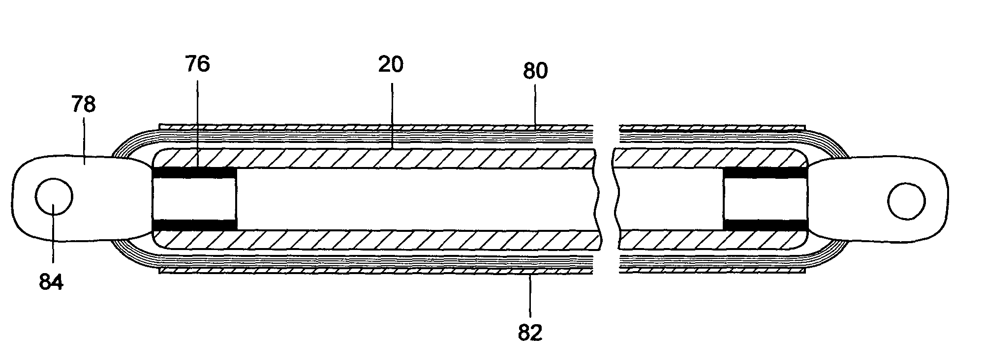
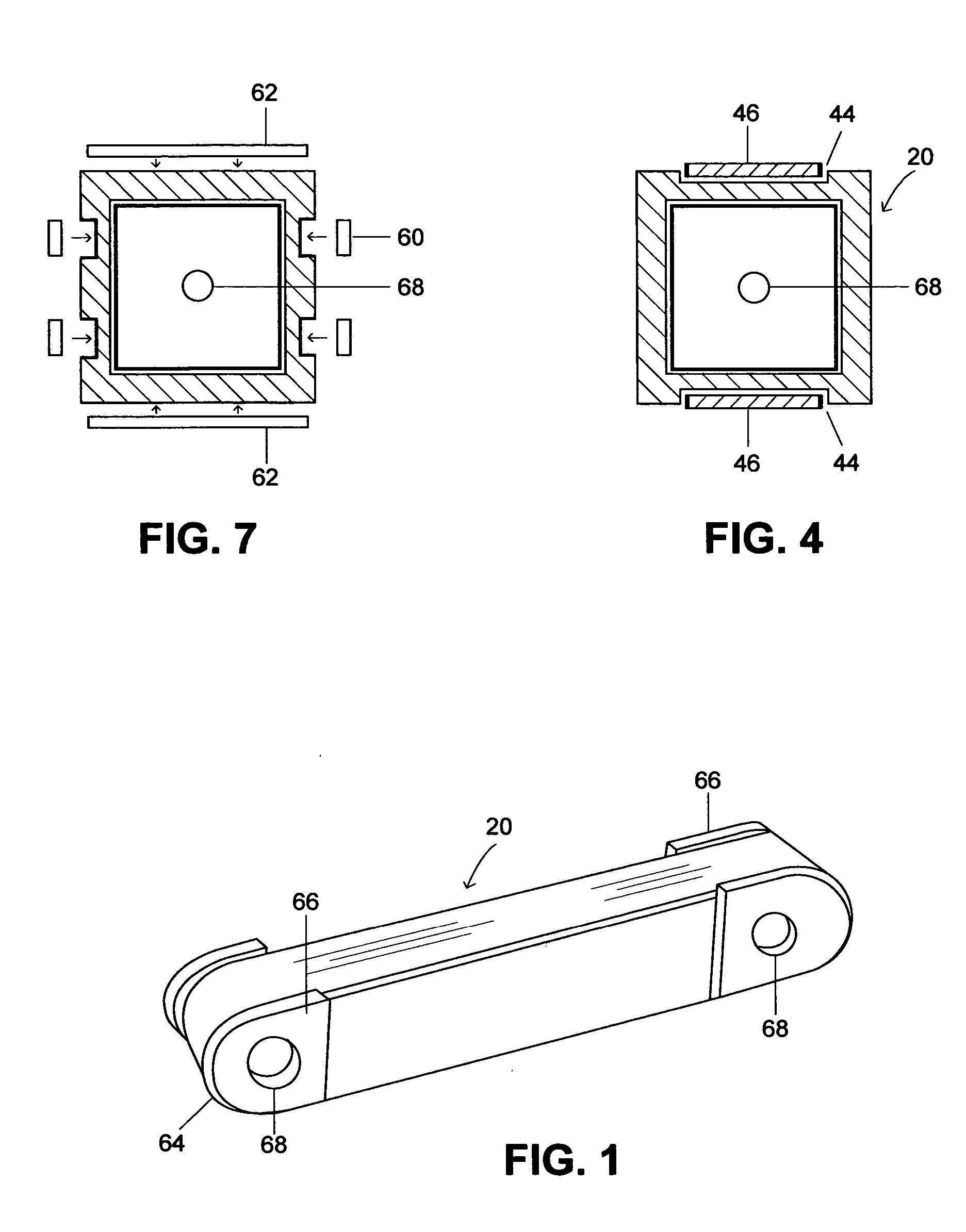
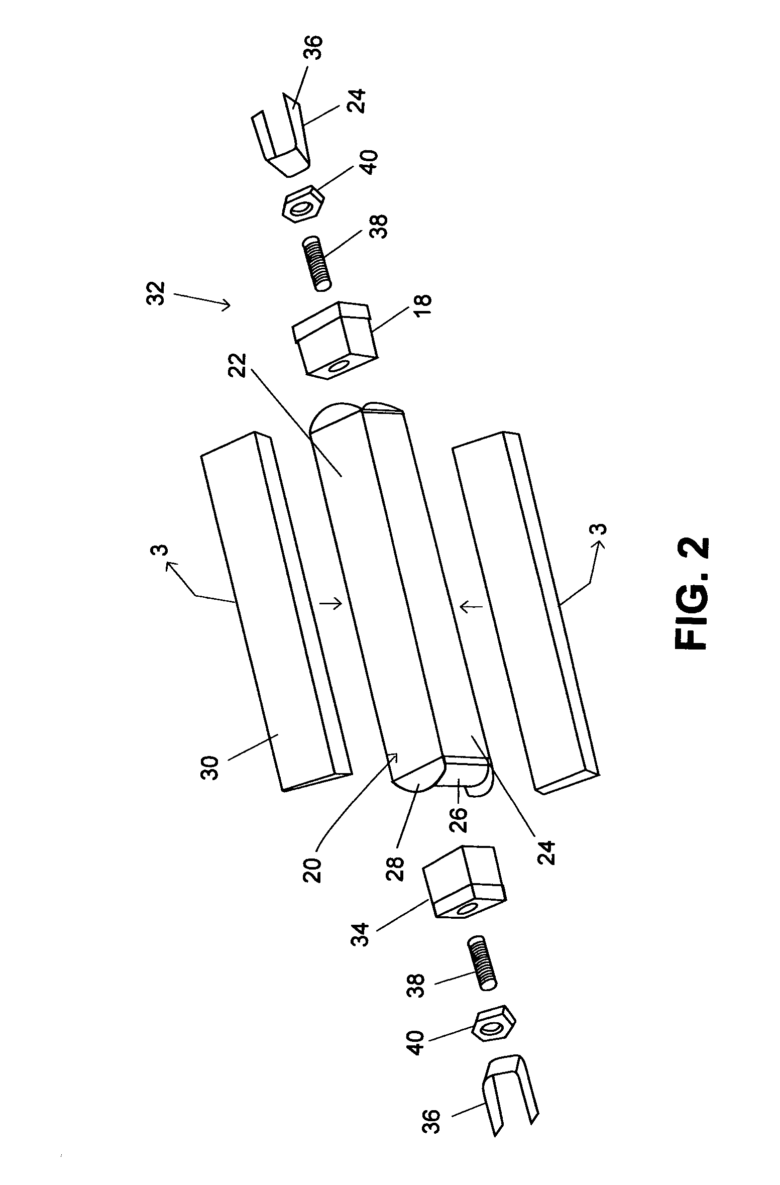
[0042] Referring now in more detail and by reference characters to the drawings which illustrate a preferred embodiment of the invention, 20 designates one form of strut produced in accordance with the present invention. FIG. 2 illustrates, more fully, the components forming part of the strut of FIG. 1.

[0043] The term “strut”, as used herein, is used in a broad sense to refer to any member which is capable of reacting one or more loads such as, for example, a tension load or otherwise a compression load. Other terms, such as shock absorbing units, tension tiebars, resistance assemblies and the like have been applied to members which react loads. All of these devices, regardless of the name, operate to react loads, as does a strut and, therefore, all such devices are embodied by the term “strut”.

[0044] The strut of the invention is formed with a tubular body 22 having a plurality of side walls 24 and a hollow interior 26. In the embodiment of the invention as shown in FIGS. 1, 2 an...


PUM


Abstract

A reinforced composite strut capable of reacting both compression and tension loads. The strut is preferably comprised of a fiber reinforced composite elongate body with fittings, such as metal fittings, secured to the ends thereof. The fittings may be secured by means of an adhesive and are reinforced by means of a filament band wound about the fittings and the elongate body. The strap wound upon the body allows for reacting tension loads and the body reacts to compression loads. A method of making the strut is also disclosed.

Description

BACKGROUND OF THE INVENTION [0001] 1. Field of the Invention [0002] This invention relates in general to certain new and useful improvements in load bearing struts and, more particularly, to load bearing struts which are capable of effectively and efficiently reacting to compressive loads and tension loads in the same strut. [0003] 2. Brief Description of Related Art [0004] Although struts were made primarily of metals such as steel and even stainless steel, with the recognition that reinforced composites are effective and even more efficient substitutes, many struts are made of reinforced composite materials. While reinforced composites provide lighter weight and, in many cases, stronger reinforcement than that provided by the metal counterparts, they are limited in terms of reacting to a variety of force loads. Thus, and while a reinforced composite strut is effective in reacting to tension loads, it may not be effective in reacting to compressive loads and vice versa. [0005] Stru...

Claims


Application Information

Patent Timeline
Patent Type & Authority Applications(United States)
IPC IPC(8): B60G7/00B64C1/00B64C13/30E04C3/28E04C3/29
CPCB60G7/001B60G2206/11B60G2206/7101B64C1/06B64C13/30Y10T74/2142E04C3/28E04C3/29Y02T50/433Y02T50/44B64C2001/0072B60G2206/85Y02T50/40
Inventor JONES, BRIAN H.
Owner KAISER COMPOSITEK
Why Eureka
Try Eureka