Oil supply structure for continuously variable valve timing apparatus

a technology of oil supply structure and valve timing apparatus, which is applied in valve arrangement, pressure lubrication, machines/engines, etc., can solve the problems of reducing revolution and viscosity, and achieve the effect of reliable respons

Inactive Publication Date: 2005-03-03
HYUNDAI MOTOR CO LTD
View PDF0 Cites 6 Cited by
  • Summary
  • Abstract
  • Description
  • Claims
  • Application Information

AI Technical Summary

Benefits of technology

[0007] The present invention provides an oil supply structure for a continuously variable valve timing apparatus adapted to automatically increase oil pressure supplied to the continuously variable valve timing apparatus when oil temperature rises, thereby enabling the continuously variable valve timing apparatus to provide a reliable response over an entire operating range of an engine.

Problems solved by technology

When engine revolution is low and oil temperature is high, there are cases where oil pressure becomes low enough to prevent the variable valve timing apparatus from being fully supplied with oil.
However, there is a drawback in that the response of a continuously variable valve timing apparatus is decreased when oil temperature is increased to result in a decrease in viscosity and engine revolution is decreased to reduce the output pressure of an oil pump although a cam shaft should overcome an operational friction for rotation and a high oil pressure is needed during a control of an advanced angle.

Method used


Image

  • Oil supply structure for continuously variable valve timing apparatus
  • Oil supply structure for continuously variable valve timing apparatus
  • Oil supply structure for continuously variable valve timing apparatus

Examples


Embodiment Construction

[0014] A preferred embodiment of the present invention will now be described in detail with reference to the annexed drawings, where the present embodiment is not limiting the scope of the present invention but is given only as an illustrative purpose.

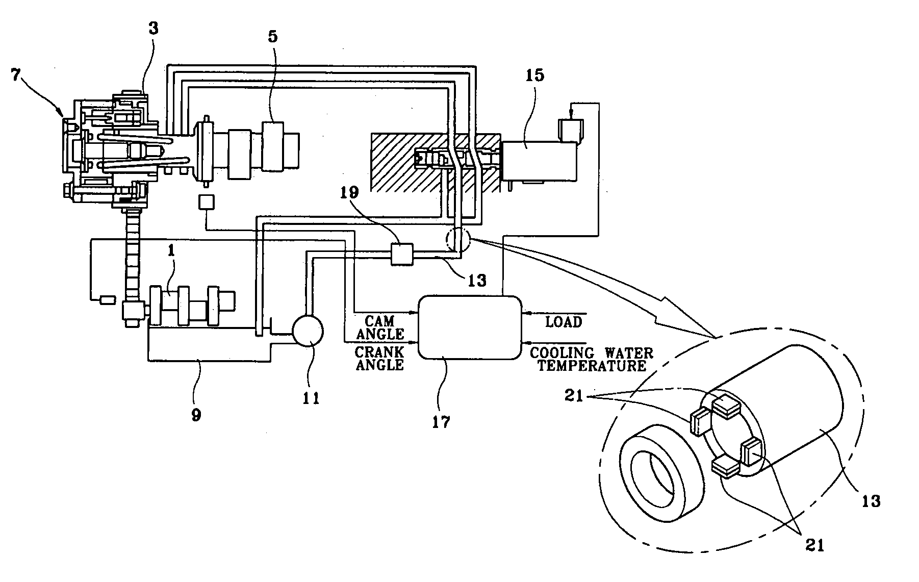
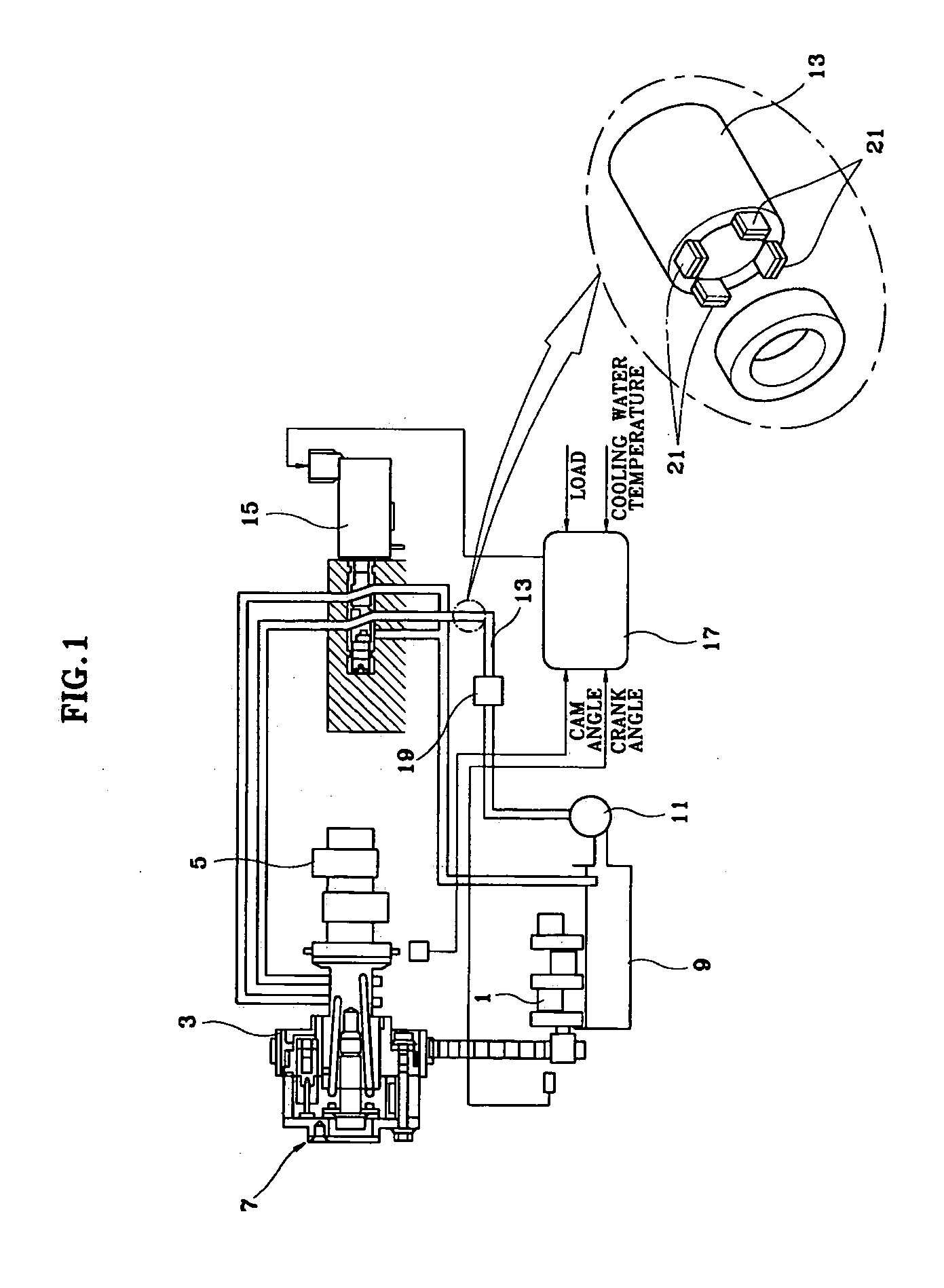
[0015] Referring to FIG. 1, an oil supply structure for a continuously variable valve timing apparatus according to a preferred embodiment of the present invention includes a rotor vane type actuator 7 mounted between a cam shaft sprocket 3 and a cam shaft 5 to enable a rotation of the cam shaft 5 relative to the cam shaft sprocket 3. Sprocket 3 is connected to a crankshaft 1 by a belt or chain. An oil control valve 15 is also disposed for receiving oil pumped by an oil pump 11 from an oil pan 9 via an oil supply pipe 13 and supplying the oil to the variable valve timing actuator 7 by adjusting an oil passage.

[0016] The oil control valve 15 is controlled by an electric signal provided from a controller 17 for receiving signals of var...


PUM


Abstract

An oil supply structure for a continuously variable valve timing apparatus wherein a plurality of bimetal blocks change in shape based on oil temperature in an oil supply pipe, whereby, when an oil temperature rises, oil pressure supplied to a variable valve timing apparatus is automatically increased to provide the variable valve timing apparatus with a reliable response over an entire operating range.

Description

CROSS-REFERENCE TO RELATED APPLICATIONS [0001] This application claims priority of Korean Application No. 10-2003-0061475, filed on Sep. 3, 2003, the disclosure of which is incorporated fully herein by reference. FIELD OF THE INVENTION [0002] The present invention relates to an oil supply structure for a continuously variable valve timing apparatus and, more particularly, to an oil supply structure for improving the response of a continuously variable valve timing apparatus. BACKGROUND OF THE INVENTION [0003] A rotor vane type continuously variable valve timing apparatus compares a rotating phase of a cam shaft with that of a cam shaft sprocket to rotate a cam shaft relative to a cam shaft sprocket to thereby advance or delay the rotating phase of the cam shaft. In other words, when a rotating phase of a cam shaft is to be delayed in comparison with a cam shaft sprocket, the cam shaft is rotated in the opposite rotating direction of the cam shaft sprocket relative to the cam shaft s...

Claims


Application Information

Patent Timeline
Patent Type & Authority Applications(United States)
IPC IPC(8): F01L1/34F01M1/16F01M1/06
CPCF01L1/022F01L1/024F01L1/34F01L2101/00F01L2001/34436F01L2001/3444F01L2001/34426F01L2301/00
Inventor BU, SUNG-HYUP
Owner HYUNDAI MOTOR CO LTD
Why Eureka
Try Eureka