Decision method of a production parameter of an injection molding, production method of a injection molding, injection molding device and program

a production parameter and decision method technology, applied in the direction of manufacturing tools, auxillary shaping apparatus, instruments, etc., can solve the problems of difficult to control a complexly-shaped weld line, difficult to apply the technology to products having general shapes, and difficult to predict how much time lag in injection timing will be sufficient, etc., to reduce the device cost and the running cost increase, and the capacity of the mold clamping force.

Inactive Publication Date: 2005-03-03
SUMITOMO CHEM CO LTD
View PDF7 Cites 17 Cited by
  • Summary
  • Abstract
  • Description
  • Claims
  • Application Information

AI Technical Summary

Benefits of technology

The present invention, in view of the foregoing problems, has an object to provide a method for determining a production parameter of an injection molding through prompt calculation of an adequate production parameter without repeating manual trial and error, which can optimize injection molding including reduction of the mold clamping force required for molding and suppression of weld line occurrence, to provide a production method of an injection molding, to provide an injection molding device, and to provide a program therefor.
The present invention is highly effective, for example, in controlling the mold clamping force required for injection molding.
A preferable production parameter is a parameter to control the action of inflow regulation valves positioned in resin-inflow conduits. A parameter relating to other flow rate regulation means, such as means to regulate the total resin inflow to the mold, may be used independently or may be used together with the parameter for controlling the regulation valves. Various kinds of resin are applicable as the resin material for molding depending on the target products and production conditions, and thermoplastic resin is preferred. For the case of thermoplastic resin, flow rate regulation can be done smoothly when adopting a hot runner having a heat-retaining means in the resin inflow conduit. The inflow regulation valve may be configured as what is called the valve gate.
When above-described low flow resin is molded under the conditions for high flow resin, the required mold clamping force becomes enormous, exceeding the capacity of mold clamping force of the molding device, or the device cost and the running cost increase. The method according to the present invention, however, can decrease the mold clamping force required even for such resin. Therefore, the molding device with smaller mold clamping force can be used for molding, or the energy cost or other costs for molding can be reduced.
The present invention is highly effective also for the case of controlling weld line occurrence.

Problems solved by technology

According to the technology disclosed on the aforementioned Japanese Patent Laid-open Gazette No. 2002-355866, page 2, it is difficult to apply the technology to products having general shapes, though a longitudinally extending shape molding allows easy judgment on timing determination of injection time-intervals.
This is because in the case of the general shapes it is very difficult to predict how much time lag in injection timing will be sufficient to produce a desired effect.
Consequently, it is difficult to control a complexly-shaped weld line where the resin flows from three directions merge.

Method used


Image

  • Decision method of a production parameter of an injection molding, production method of a injection molding, injection molding device and program
  • Decision method of a production parameter of an injection molding, production method of a injection molding, injection molding device and program
  • Decision method of a production parameter of an injection molding, production method of a injection molding, injection molding device and program

Examples


first embodiment

[First Embodiment]

According to the first embodiment, the timing for opening and closing the individual valve gate is determined to minimize the maximum mold clamping force by the combination of the numerical analysis method for calculating the injection molding process and the computer-aided optimization method. Regarding the numerical analysis method for calculating the injection molding process, the method in which the behavior of resin is analyzed based on the finite element method using calculation equations on the basis of the relationship working between elements during molding, has been brought into practical application in recent years. The first embodiment adopts Moldflow Plastics Insight 2.0 rev1 (trade name, produced by Moldflow Corporation). Many similar computer-aided optimization methods have been developed. The first embodiment adopts iSIGHT 6.0 (trade name, produced by Engineous Software Inc.) as software. Since the analysis deals with a problem with intense nonline...

example 1

(8) EXAMPLE 1

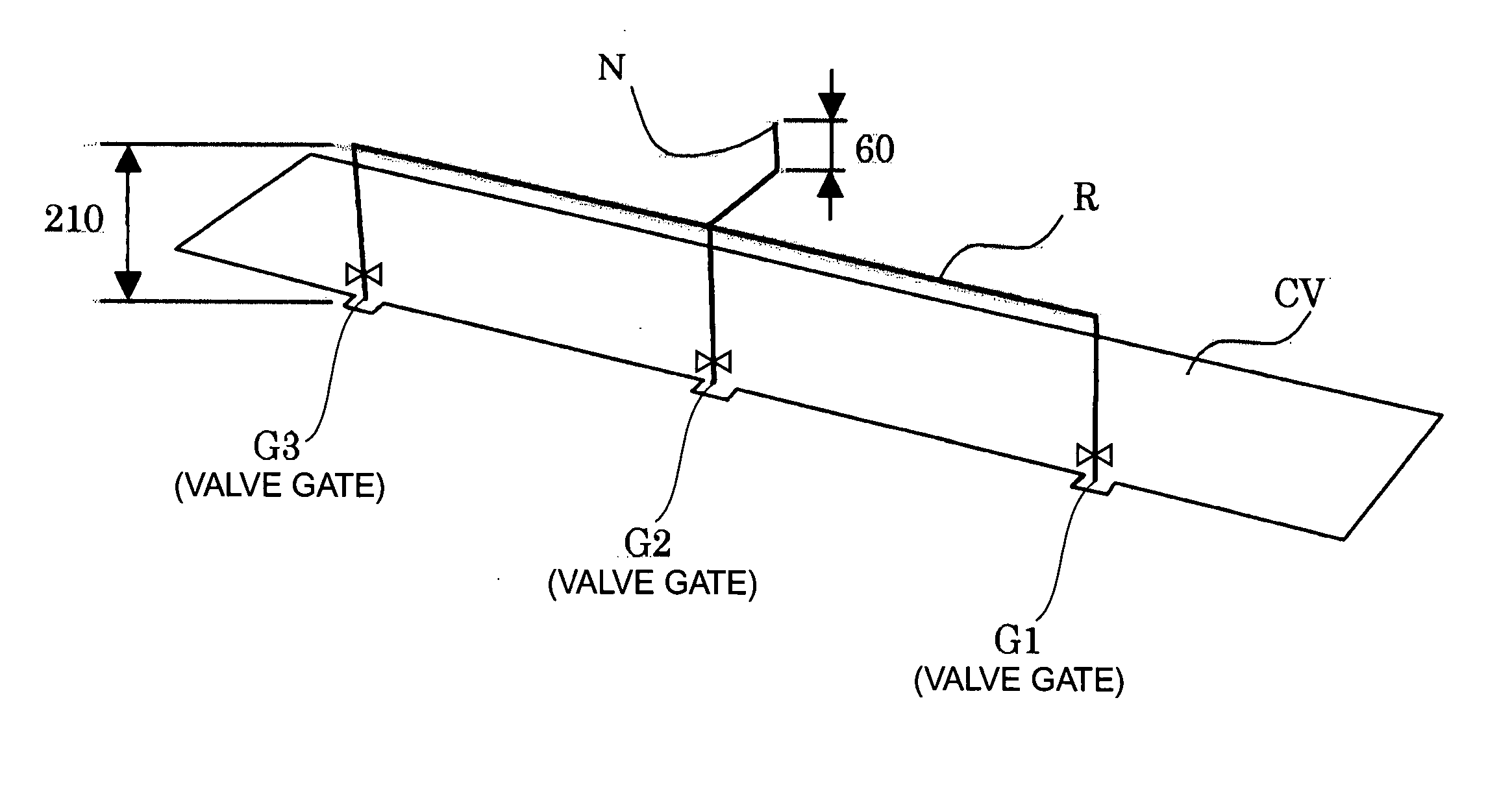
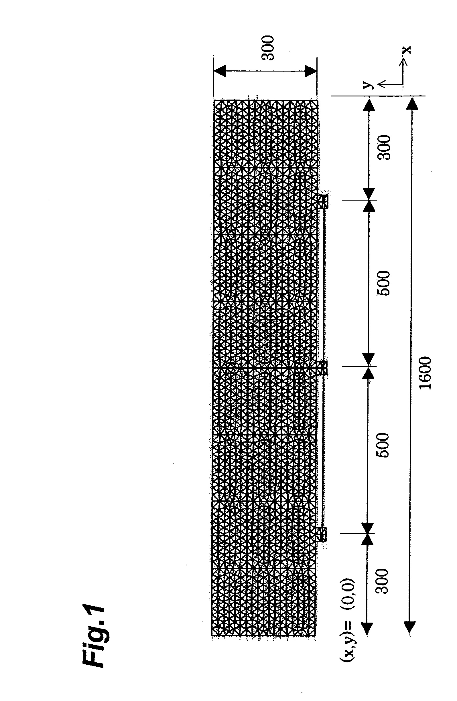
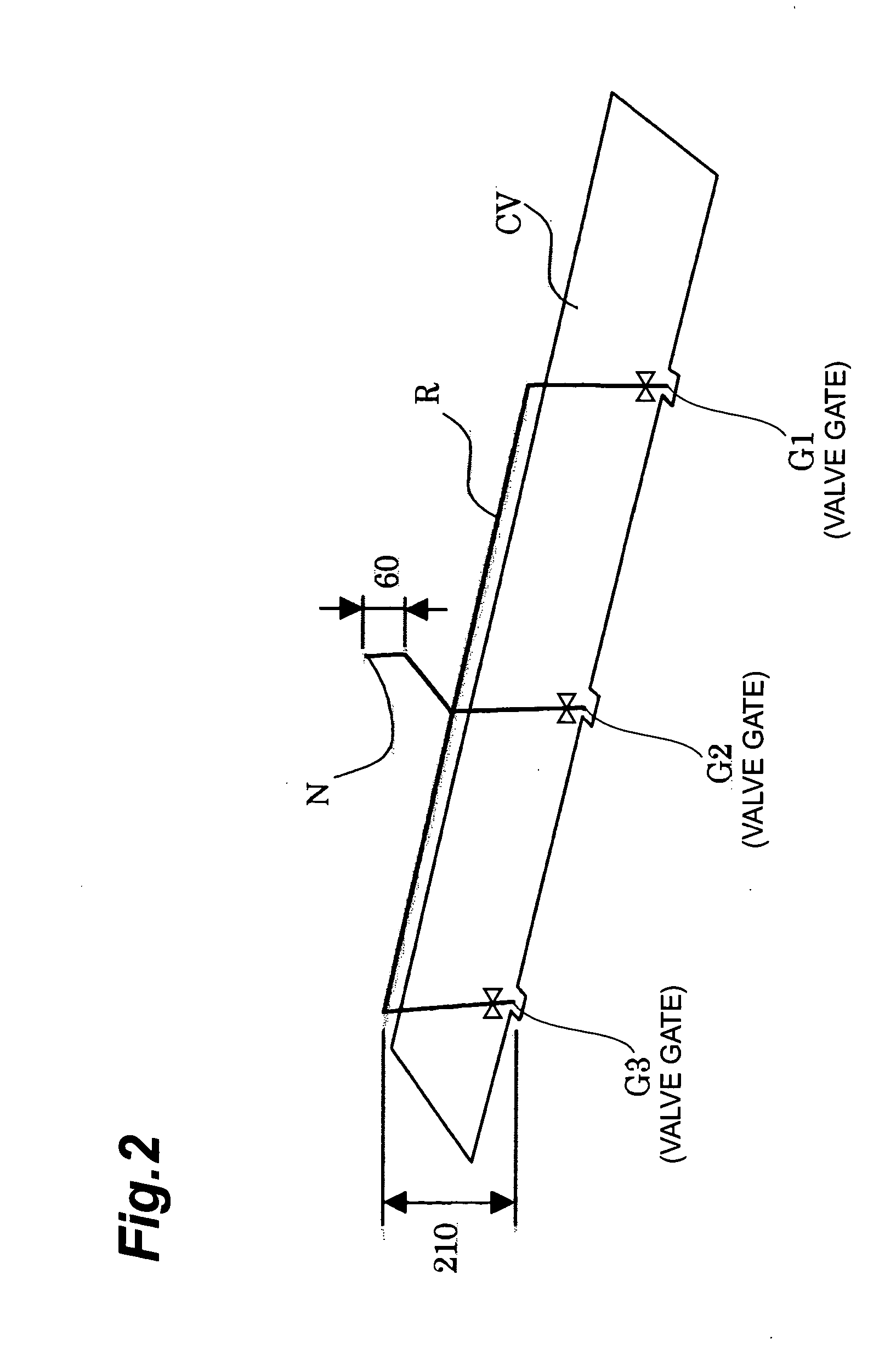
Described is one calculation example where the open / close timing for injection molding of the product shown in FIG. 1 is optimized using the above-described simulation model and method, wherein the molding is conducted by use of a material NP156 given in Table 1. The selected regulation gate is the valve gate G3 in FIG. 2. The molding conditions are resin temperature, hot runner temperature, and mold temperature of 230° C., 230° C., and 50° C., respectively, with the injection time of about 8 seconds. As for the design variables, the initial condition determined in Step 4 and the constraint condition applied in Step 9 are the following.

(1) Constraint Condition

0≦ta1≦8, 0≦tb1≦8, 0≦tc1≦8, 0≦dta≦8, 0≦dtb≦8, 0≦dtc≦8 0≦α≦1, 0≦β≦1

According to the calculation, the injection time completes in slightly less than about 8 seconds (varied with condition), therefore the upper limit of ta1, tb1, tc1, dta, dtb, dtc is selected as 8 (seconds).

(2) Initial Condition ta1=tb1=tc1=...

example 2

(10) EXAMPLE 2

A description of one calculation example is given below for optimizing the open / close timing of injection molding product shown in FIG. 1 using the above-described simulation model and method for the case that the molding is conducted using the material AH561, a low flow resin (MFR=3) shown in Table 1. The molding conditions are resin temperature, hot runner temperature, and mold temperature of 220° C., 220° C., and 50° C., respectively, with the injection time of about 6 seconds. As for the design variables, the initial condition determined in Step 4 is the same as that of Example 1 except for dta=6, and the constraint condition applied in Step 9 is the same as that of Example 1 except that the upper limit of ta1, tb1, tc1, dta, dtb, dtc is selected as 6 (seconds). As a comparative example, calculations were carried out for the material AH561 without gate open / close control (always open), under the temperature conditions where the resin temperature, the hot runner te...


PUM

PropertyMeasurementUnit
temperatureaaaaaaaaaa
diameteraaaaaaaaaa
diameteraaaaaaaaaa

Abstract

An object of the present invention is to achieve favorable injection molding with reduced mold clamping force required for molding and with suppression of weld line occurrence without repeating trial and error manually, by prompt calculation of adequate production parameters, when conducting injection molding of resin products. When the injection molding is conducted using a mold having a plurality of resin inflow conduits N, R, G1, G2, and G3 to the cavity CV, the combination of a numerical analysis method for calculating the injection molding process and a computer-aided optimization method, derives the production parameters which determine time-sequentially the inflow of resin material through resin inflow conduits.

Description

BACKGROUND OF THE INVENTION 1. Field of the Invention The present invention relates to a method for determining a production parameter in the case of injection molding of resin, a method for producing an injection molding using the production parameter, an injection molding device, and a program. 2. Related Background Art When molding resin with an injection molding device, there is a demand to minimize the mold clamping force necessary for molding. Normally, the mold clamping force of a device is predetermined by using a safety factor allowance as well as the mold clamping force required for molding, therefore the smaller the required mold clamping force for molding, the less the output of the pressure generating system in a injection molding device is required. Accordingly, if the device can be substituted for a smaller one, the running cost decreases, and this is the reason why there is such a demand to minimize mold clamping force. Furthermore, even in the case of the identi...

Claims


Application Information

Patent Timeline
Patent Type & Authority Applications(United States)
IPC IPC(8): B29C45/28B29C45/76
CPCB29C45/28B29C45/7693B29C47/92B29C2945/76505B29C2945/76548B29C2045/0032
Inventor NAGAOKA, SHINICHIHIROTA, TOMOOTOGAWA, YOSHIAKI
Owner SUMITOMO CHEM CO LTD
Why Eureka
Try Eureka