Linear motor with reduced cogging force

Active Publication Date: 2005-03-03
SANYO DENKI CO LTD
View PDF4 Cites 13 Cited by
  • Summary
  • Abstract
  • Description
  • Claims
  • Application Information

AI Technical Summary

Benefits of technology

[0010] It is preferable that the curved surfaces are so formed to satisfy a relationship of 0.38≦Lt/R≦0.65, where Lt is a length between a lower end of the curved surface, and an intersection of a virtual line passing through the lower end of the curved surface and extending in parallel to the magnetic pole row and a virtual perpendicular passing through an upper end of the curved surface and orthogonally crossing the virtual line (Lt is the shortest distance between a perpendicular passing through the lower end and a perpendicular passing through the upper end) and R is a radius of the arc. If the curved surfaces are formed as described above, the cogging force can be reduced, and a variation in the cogging force can also be reduced even if the mounting accuracy of the armature is not increased. When the ratio Lt/R becomes less than 0.38, the cogging force cannot be reduced. When the ratio Lt/R exceeds 0.65, the total length of the armature increases, and the mass of the armature also increases.
[0011] It is preferable that an angle α° between a virtual line that extends in parallel to the magnetic pole row and a tangent that passes through the lower end of the curved surface satisfies a relationship of 0°≦α°≦10°. If the angle α° is set as described above, the cogging force can be reduced and a variation in the cogging force can also be reduced even if the positioning accuracy of permanent magnet arrangement is not increased. When the angle α° exceeds 10°, the cogging force cannot be reduced, and a variation in the cogging force becomes larger.
[0012] In a vicinity of the magnetic pole surface of each of two pole teeth located at both ends of the pole tooth row, one or more holes or cavities extending in the laminating direction of the electromagnetic steel plates can be formed. The holes or cavities may be through holes, closed-end holes, or cavities. By defining the positions and the number of the holes or cavities appropriately, magnetic resistance inside each of the pole teeth can be changed, and the magnetic characteristic on the side of the pole teeth can be modified to reduce the cogging force, even if the size of a gap formed between each curved surface and the magnetic pole row remains the same.
[0013] Magnetic pieces having a length shorter than the thickness of the electromagnetic steel plates in their laminating direction can be arranged in one or more of the holes or cavities. With this arrangement, inside the pole teeth, the magnetic resistance in the portions where the magnetic pieces are present becomes smaller tha

Problems solved by technology

In the linear motor of this type, however, large cogging force is generated.
Thus, it was difficult to form the optimum ar

Method used


Image

  • Linear motor with reduced cogging force
  • Linear motor with reduced cogging force
  • Linear motor with reduced cogging force

Examples


Embodiment Construction

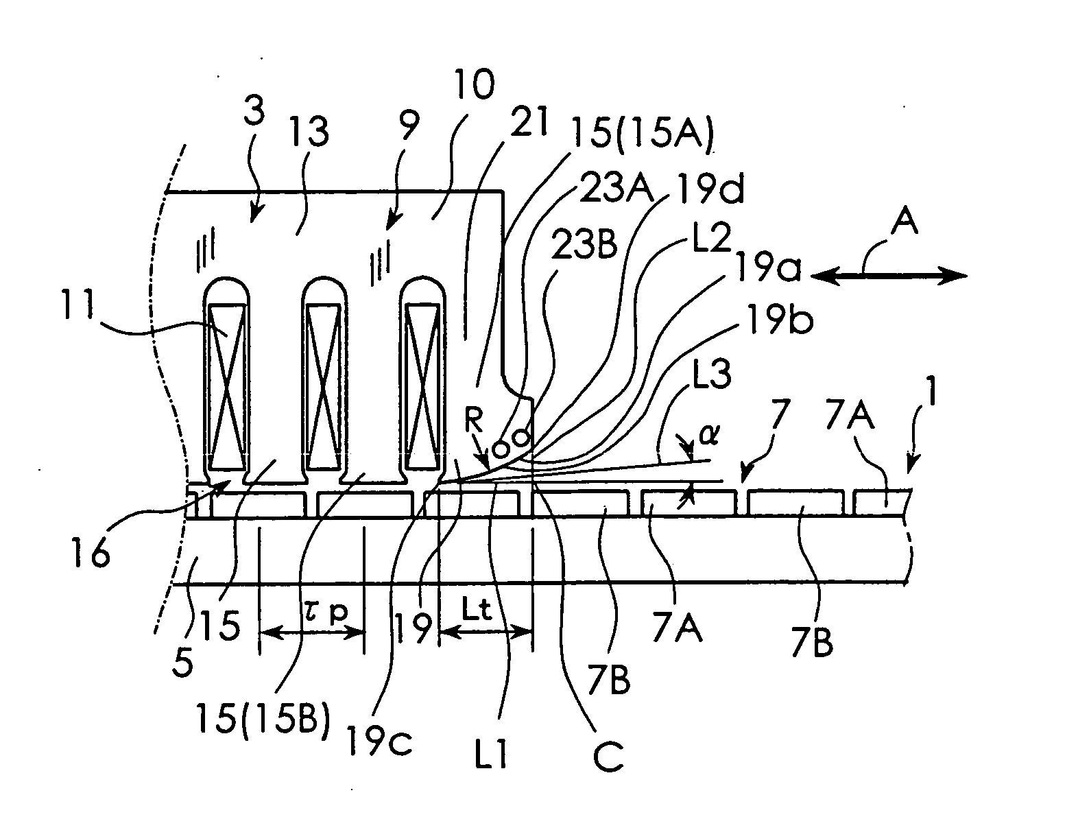
[0020] The best mode for carrying out the present invention will be described with reference to the appended drawings. FIG. 1 is a schematic diagram used to explain the construction of a linear motor according to a first embodiment of the present invention. FIG. 1 shows part of a stator 1 and part of a movable element 3. As shown in FIG. 1, the linear motor according to this embodiment includes the stator 1 and the movable element 3. The stator 1 has a structure provided with a magnetic pole row 7 on a base 5. The magnetic pole row 7 is constituted by alternately arranging a plurality of N-pole permanent magnets 7A and a plurality of S-pole permanent magnets 7B.

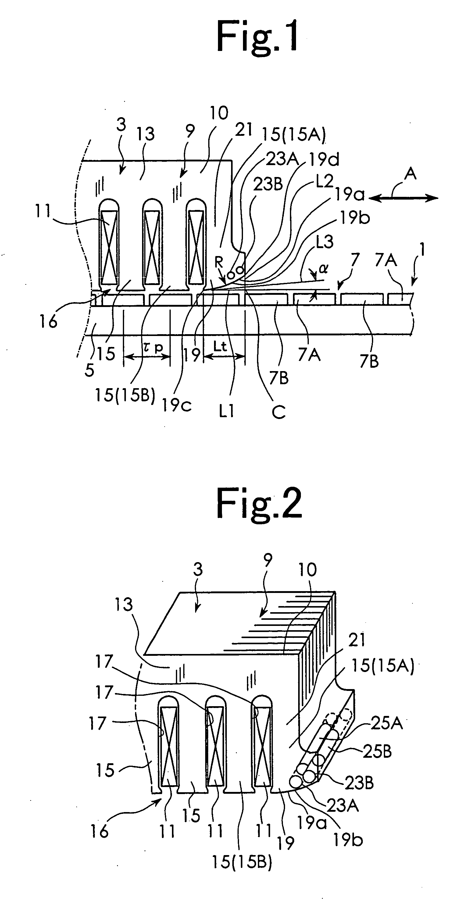
[0021] The movable element 3 is movably supported by supporting means not shown, relative to the stator 1. The movable element 3 includes an armature constituted by a core 9 and multi-phase exciting windings 11 as shown in a perspective view of FIG. 2. The core 9 is constituted by laminating a plurality of electromagnetic st...


PUM


Abstract

A linear motor in which the shape of magnetic pole surfaces of pole teeth located at both ends of a plurality of pole teeth can be easily formed to be suitable for reducing cogging force. Each of magnetic pole surfaces 19a of pole teeth 15A located at both ends of a plurality of pole teeth 15 is constituted by an arc-shaped curved surface that is curved so that gap from a stator 1 increases with increasing distance from other adjacent pole tooth 15B. Through holes 23A and 23B that extend in the laminating direction of electromagnetic steel plates 10 are formed in the vicinity of the magnetic pole surfaces 19a of the pole teeth 15A. Inside the through holes 23A and 23B, magnetic pieces, which are shorter than the thickness of the electromagnetic steel plates in their laminating direction, are arranged so as to leave spaces at both ends of the through holes 23A and 23B.

Description

BACKGROUND OF THE INVENTION [0001] The present invention relates to a linear motor. [0002] As an example of a linear motor in which a movable element reciprocates linearly relative to a stator, the linear motor has an armature and at least one row of magnetic poles formed by juxtaposedly arranging a plurality of permanent magnets. The armature has a core which is constituted by laminating a plurality of electromagnetic steel plates and exciting windings. The core has a yoke that extends linearly in a direction orthogonal to the direction in which the electromagnetic steel plates are laminated, and a plurality of pole teeth that protrude from the yoke toward the magnetic pole row side and have magnetic pole surfaces opposed to the row of magnetic poles or magnetic pole row at their ends. A plurality of the exciting windings excite the pole teeth. In the linear motor of this type, however, large cogging force is generated. Thus, in order to solve this problem, there has been proposed ...

Claims


Application Information

Patent Timeline
IPC IPC(8): H02K41/03H02K41/02
CPCH02K41/031H02K15/03H02K33/18
Inventor SUGITA, SATOSHIMISAWA, YASUSHI
Owner SANYO DENKI CO LTD
Why Eureka
Try Eureka