Movable assembly for cylinder type linear motor

Inactive Publication Date: 2005-03-03
SANYO DENKI CO LTD
View PDF6 Cites 27 Cited by
  • Summary
  • Abstract
  • Description
  • Claims
  • Application Information

AI Technical Summary

Benefits of technology

[0027] The magnetic member may be provided in the form of a cylindrical portion into which the direct drive shaft is inserted. With this arrangement, although the number of parts increases, the cylindrical portion can strengthen the laminated yoke. Further, by setting a desired shape of the outline of the cross section of the cylindrical portion, an appropriate rotation prevention and positioning of the electromagnetic steel plates relative to the cylindrical portion can be assured.
[0028] The cylindrical portion of the magnetic member is preferably integrally formed at one end with a flange portion that engages an end face of the laminated yoke in the lamination direction. The flange portion prevents the laminated yoke from directly abutting against a case of the cylinder type linear motor, thereby protecting the movable assembly against possible damages. The flange portion may also be formed with tapped holes extending therethrough in the direction of lamination and fastened with screws inserted from a side of the laminated yoke opposite the side abutting the flange portion, thereby connecting the magnetic member and the laminated yoke together firmly and easily.
[0029] The laminated yoke may have a square-columnar structure whose cross section in the direction orthogonal to the direct drive shaft is polygonal. The laminated yoke may also have on its outer circumference a plurality of permanent magnet mounting surfaces extending parallel to the direct drive shaft. In that case, it is preferred that the laminated yoke have formed therein a plurality of magnetic member receiving holes which correspond to the plurality of the permanent magnet mounting surfaces and that a plurality of divided magnetic bodies making up the magnetic member be fitted individually into the plurality of magnetic member receiving holes. With this arrangement, good magnetic paths can be formed, reducing the magnetic resistance of the movable cor

Problems solved by technology

With this arrangement, magnetic fluxes flow between the opposing permanent magnets through the laminated yoke, which makes it difficult for the magnetic fluxes to flow in the direction of lamination of electromagnetic steel plates.
If the cross sectio

Method used


Image

  • Movable assembly for cylinder type linear motor
  • Movable assembly for cylinder type linear motor
  • Movable assembly for cylinder type linear motor

Examples


Embodiment Construction

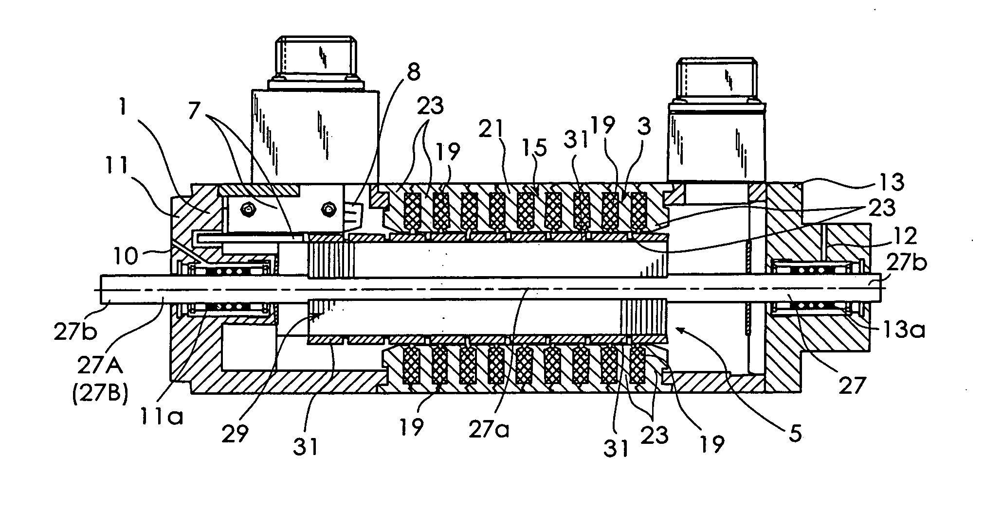
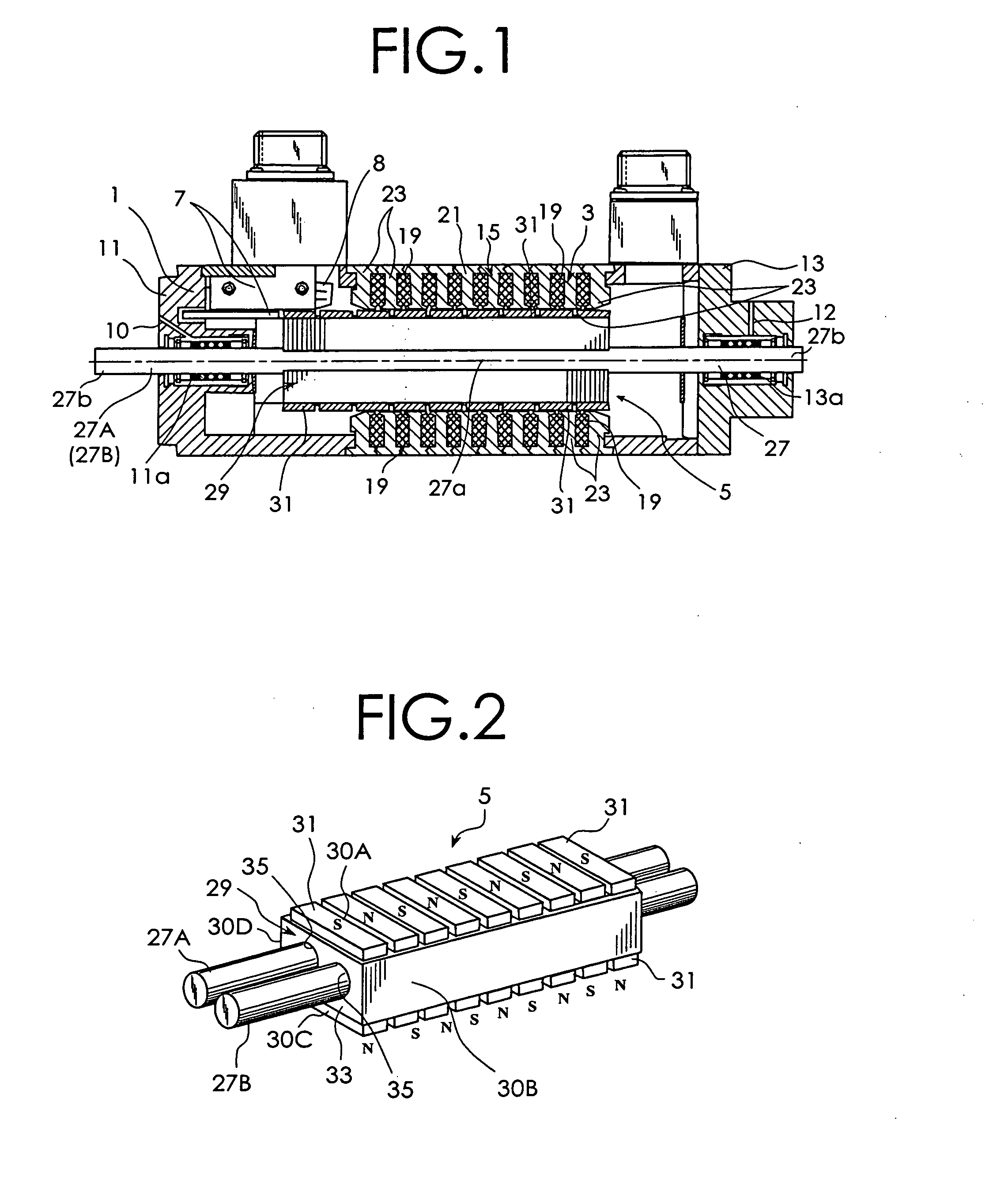
[0053] A preferred embodiment of this invention will be described by referring to the accompanying drawings. FIG. 1 is a cross-sectional view of a cylinder type linear motor with a movable assembly of one embodiment of this invention. As shown in FIG. 1, the cylinder type linear motor has a case 1, a stator 3, a movable assembly 5, and a linear sensor 7 to detect a position of the movable assembly 5. The case 1 has paired end brackets 11, 13 made of nonmagnetic material (e.g., aluminum). The end brackets 11, 13 are fixed to the ends of a stator core 15 of the stator 3 described later.

[0054] The stator 3 has the cylinder type stator core 15 and a plurality of excitation windings 19. The stator core 15 is situated between the end brackets 11, 13. The stator core 15 has a yoke 21 and a plurality of magnetic poles 23 arranged at predetermined intervals in an axial direction of the movable assembly 5. The construction of the stator core 15 is well known and thus its explanation is omitt...


PUM


Abstract

A movable assembly used in a cylinder type linear motor is provided which can be manufactured at low cost without requiring a cutting process while preventing its magnetic characteristics from deteriorating. The movable core is constructed of a laminated yoke which is formed of a plurality of electromagnetic steel plates laminated in an axial direction of the first and second direct drive shafts. A plurality of permanent magnets 31 fixed to the laminated yoke 29 are arranged in such a manner that the polarity appearing on the outer surface of the two permanent magnet 31 opposing each other through the laminated yoke 29. The first and second direct drive shafts each have a yoke mounting portion and paired supported portions at both axial ends of the yoke mounting portion. The first and second direct drive shafts are so shaped that the cross section of the yoke mounting portion orthogonal to the axial direction is smaller than that of the supported portions. Each of the electromagnetic steel plates is made up of first and second divided electromagnetic steel plate pieces of the same shape.

Description

BACKGROUND OF THE INVENTION [0001] The present invention relates to a movable assembly used in a cylinder type linear motor that reciprocally moves inside a stator of the cylinder type linear motor. [0002] In conventional cylinder type linear motors, a movable core, considering a path of magnetic flux, employs a laminated structure in which silicon magnetic steel plates are laminated in such a manner that a radial direction of a direct drive shaft, on which the movable core is securely mounted, is a direction of lamination. Such a laminated structure is shown in FIG. 7 of Japanese Patent Disclosure No. 2000-236653. Japanese Patent Disclosure No. 2002-359962 discloses a construction of another cylinder type linear motor that this applicant proposed previously. In the cylinder type linear motor shown in the previous application, an array of permanent magnets is mounted on a square-columnar structured magnet mounting portion of the movable assembly. [0003] The conventional movable core...

Claims


Application Information

Patent Timeline
IPC IPC(8): H02K1/34H02K33/16H02K41/02H02K41/03
CPCH02K1/278H02K1/34H02K33/16H02K1/30H02K1/276H02K1/28H02K41/031H02K41/03H02K41/02
Inventor TANG, YUGISUGITA, SATOSHI
Owner SANYO DENKI CO LTD
Why Eureka
Try Eureka