Charge pump circuit with current detecting and method thereof

a charge pump and current detection technology, applied in pulse generators, pulse techniques, instruments, etc., can solve the problems of not being able to tolerate led emission spectrum drift, not being able to drive the light source, and significantly increasing the manufacturing cost and pcb area occupation, so as to achieve the effect of stabilizing the current passing through the load circui

Active Publication Date: 2011-02-24
GREEN SOLUTION TECH CO LTD
View PDF10 Cites 14 Cited by
  • Summary
  • Abstract
  • Description
  • Claims
  • Application Information

AI Technical Summary

Benefits of technology

[0013]Therefore, the embodiments according to the present invention provide a charge pump circuit with feedback current detecting, wherein the feedback circuit unit of the charge pump circuit adjusts the controlled current source of the charge pump circuit unit based on a feedback current, thereby stabilizing the current passing through the load circuit; and furthermore, a protecting circuit unit is provided which protects the circuitry in the feedback circuit from possible occurrences of over-current or under-current damages to the load circuit and the charge pump circuit.

Problems solved by technology

Especially, for portable devices using batteries as their power sources, since such batteries may be merely able to provide low voltage power, they are not suitable for driving the light source composed of multiple LED's connected in series.
Typically the boost DC-DC converter which is utilized to increase battery voltages, provides high conversion efficiency, but undesirably leads to significantly increase in manufacturing cost and PCB area occupation as well.
For certain high-leveled products, or devices particularly sensitive to luminance chromaticity, e.g., monitors, such drifts of the LED emission spectrum can not be tolerated.
Since the portable device usually employs batteries as its power source, sudden output of massive current may lead to dramatic falloff in the battery voltage.
As a result, other circuits may be inevitably interfered by the surges shown in FIG. 3; for example, noises may be generated in an audio circuit and the like.

Method used


Image

  • Charge pump circuit with current detecting and method thereof
  • Charge pump circuit with current detecting and method thereof
  • Charge pump circuit with current detecting and method thereof

Examples


first embodiment

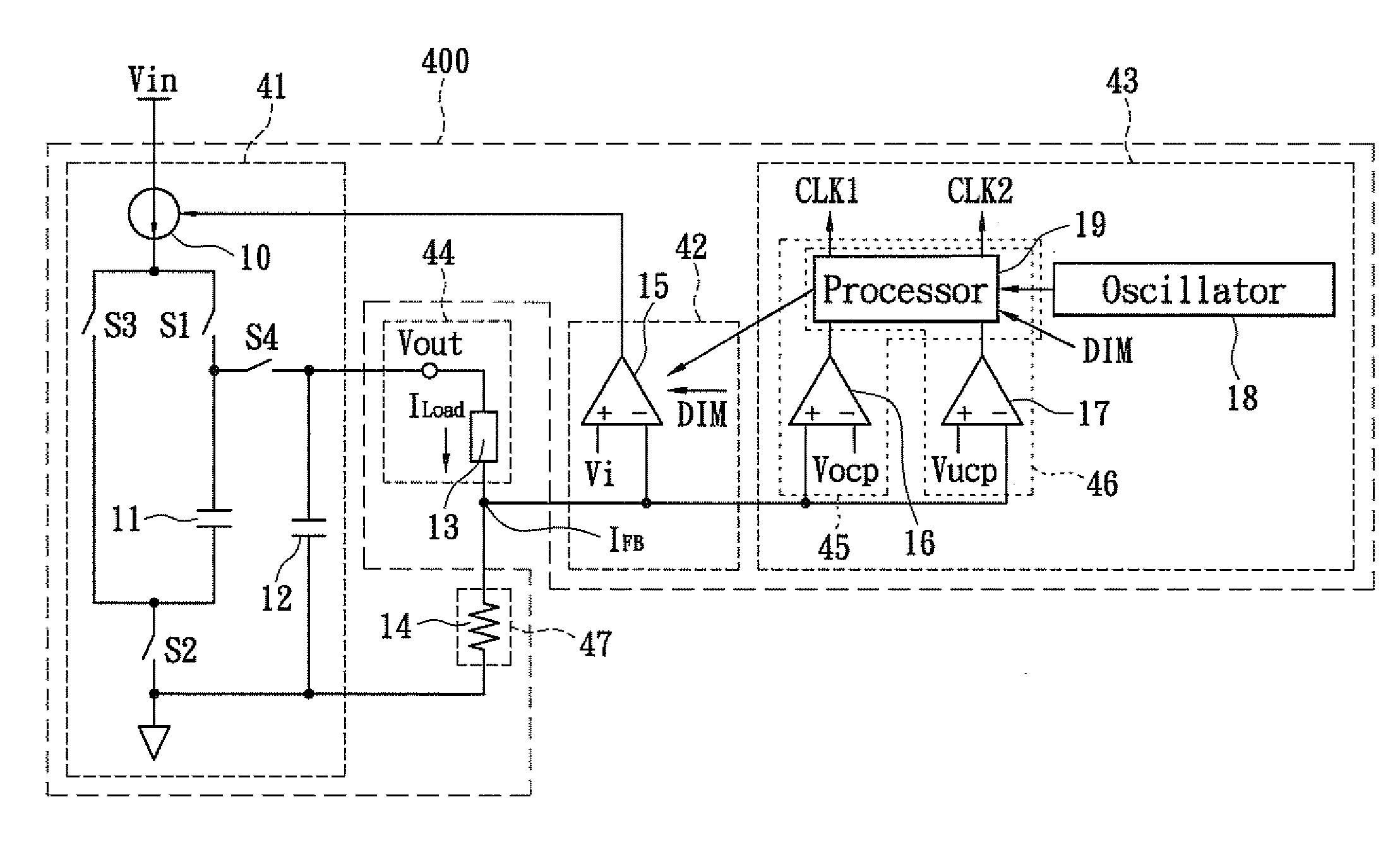
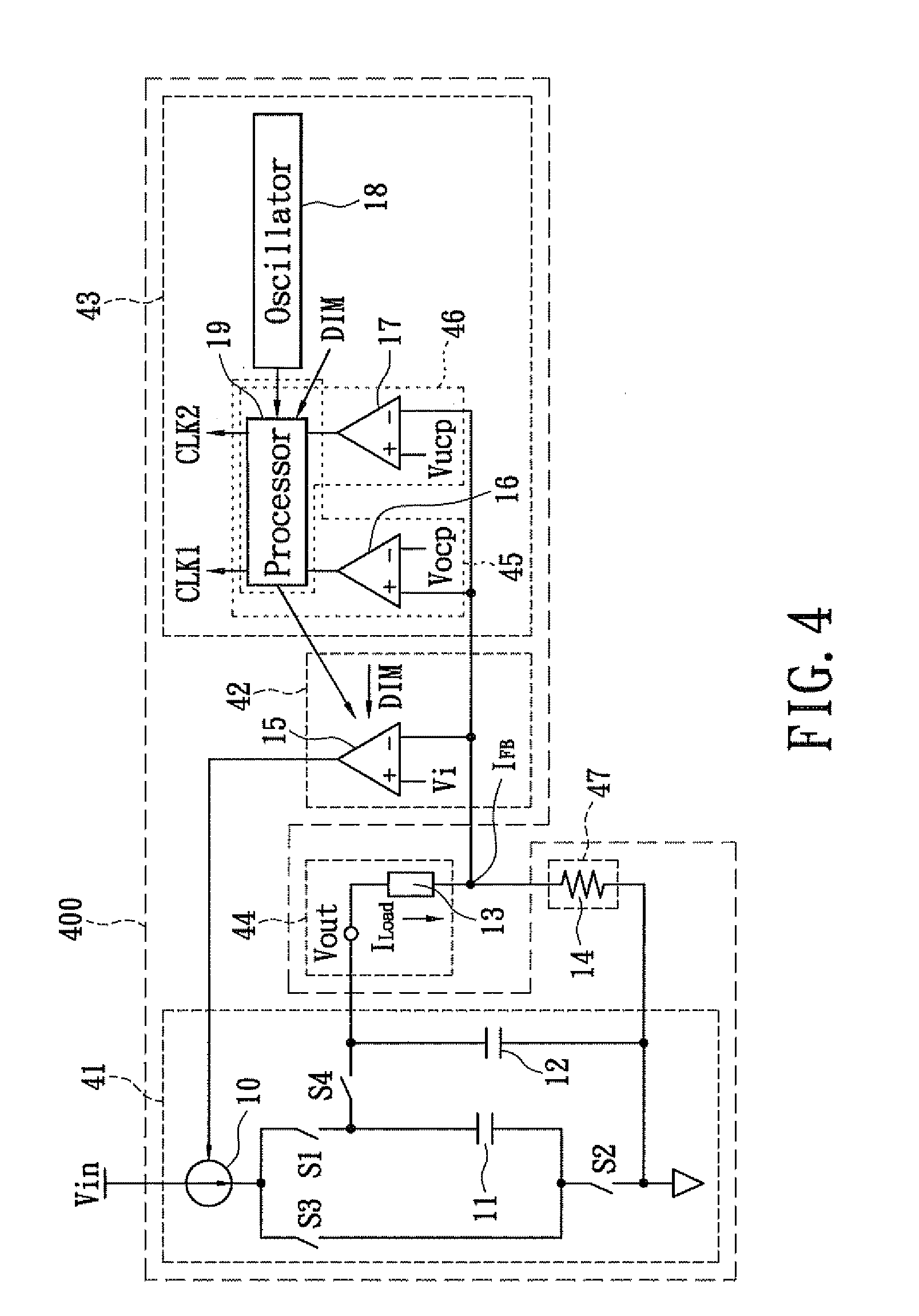
[0028]FIG. 4 shows a circuit diagram for the charge pump circuit of a first embodiment according to the present invention. The illustrated charge pump circuit 400 comprises a charge pump circuit unit 41, a feedback circuit unit 42, a protecting circuit unit 43 and a detecting circuit unit 47. The charge pump circuit unit 41 includes a controlled current source 10, switches S1, S2, S3, S4 and capacitors 11, 12. The feedback circuit unit 42 has an error amplifier 15. The protecting circuit unit 43 includes a first and a second comparators 16 and 17, an oscillator 18, a processor 19. The detecting circuit unit 47 includes a detecting resistor 14, connected to a load circuit 44 which has a load unit 13, such as at least one LED in the present embodiment, but not limited thereto for the present invention.

[0029]An input voltage source Vin is electrically connected with the controlled current source 10 of the charge pump circuit unit 41 to provide a constant voltage. The controlled current...

second embodiment

[0038]As mentioned before, because a time interval ΔT exists between the first switch signal CLK1 and the second switch signal CLK2 and all switches S1, S2, S3 and S4 are cutoff during such a time interval ΔT, the input current Iin, at this moment becomes zero. In order to stabilize the input current waveform of the input current Iin, an embodiment of a charge pump circuit 900 having a dummy path in accordance with the present invention is provided. FIG. 7 shows a circuit diagram for the charge pump circuit with a dummy path of a second embodiment according to the present invention. A dummy path P1 is added to the charge pump circuit 900, which dummy path P1 connecting the second terminal of the controlled current source 10 to ground. During the aforementioned time interval ΔT, the switches S1, S4 are cutoff and the switches S2, S3 are conductive. At this moment, the input current Lin may flow to ground through the dummy path formed by the switches S2, S3, so the input current Iin d...

third embodiment

[0040]FIG. 9 shows a circuit diagram for the charge pump circuit with a dummy path of a third embodiment according to the present invention. The charge pump circuit 1100 of the embodiment according to the present invention is additionally designed with a dummy path P2, which dummy path P2 connecting the second terminal of the controlled current source 10 to ground. The dummy path P2 comprises a switch S5, in which the first terminal of the switch S5 electrically connects to the second terminal of the controlled current source 10, while the second terminal thereof is grounded. An NAND gate 21 is herein placed whose input terminals respectively receive the first switch signal CLK1 and the second switch signal CLK2, and a third signal CLK3 is generated which controls on and off in the switch S5. That is, when the first switch signal CLK1 and the second switch signal CLK2 are both at low voltage levels, the NAND gate produces the third switch signal CLK3 which is at a high voltage level...


PUM


Abstract

The present invention relates to a charge pump circuit with current detecting and a method thereof. The current detecting charge pump circuit includes a controlled current source, a load circuit which electrically connects to the charge pump circuit unit, and is driven by the charge pump circuit unit to generate a load current. A detecting circuit unit electrically connects to the load circuit, and produces a feedback signal according to the load circuit. A feedback circuit unit which electrically connects to the detecting circuit unit, receives the feedback signal, and adjusts a current of the controlled current source according to the feedback signal. The charge pump circuit also includes a protecting circuit unit which is able to detect feedback signal to protect the circuit according to the feedback signal.

Description

BACKGROUND OF THE INVENTION[0001]1. Field of the Invention[0002]The present invention relates to a charge pump circuit; in particular, the present invention relates to a charge pump circuit with current detecting and a feedback method thereof.[0003]2. Description of Related Art[0004]Light Emitting Diodes (LED's) provide features of, among others, high luminance efficiency, high brightness, low power consumption, long lifespan, reliable security, environment friendliness and fast startup, and numerous high-technology products are now adopting LED's as their light sources for applications. In general, LED driving is commonly accomplished by means of a current source offering constant direct current, thereby maintaining the stable brightness thereof. Especially, for portable devices using batteries as their power sources, since such batteries may be merely able to provide low voltage power, they are not suitable for driving the light source composed of multiple LED's connected in serie...

Claims


Application Information

Patent Timeline
Patent Type & Authority Applications(United States)
IPC IPC(8): H05B41/36G05F1/10
CPCH02M3/07H02M2001/0087Y02B20/347Y02B20/341H05B33/0818H05B45/38Y02B20/30H02M1/0087
Inventor SHIU, SHIAN-SUNG
Owner GREEN SOLUTION TECH CO LTD
Why Eureka
Try Eureka