Multiple failure detection shutdown protection circuit for an electronic ballast

a protection circuit and electronic ballast technology, applied in the field of electronic ballast, can solve the problems of affecting the performance and operation of other systems connected to the dc bus, affecting the type of ballast circuit used for fluorescent lamps, and in some cases neon lamps suffer from certain technical problems, ac noise,

Inactive Publication Date: 2005-03-03
Q TECH CO LTD
View PDF28 Cites 25 Cited by
  • Summary
  • Abstract
  • Description
  • Claims
  • Application Information

AI Technical Summary

Problems solved by technology

Existing ballast circuits of the type used with fluorescent and, in some cases, neon lamps suffer from certain technical problems.
This causes AC noise and ripple to feed back into the DC power buss distribution system, which, in turn, can affect performance and operation of other systems connected to the DC buss.
As a result, noise or ripple may be coupled into the DC path, causing AC noise to infiltrate the DC power bus distribution system, leading to performance degradation and failure of other equipment powered by the DC buss, in some cases.
Given that it is not technically straightforward to filter out the conducted electromagnetic interference (EMI) prevalent in existing designs, the need remains for an improved filtering and control circuit configuration.

Method used


Image

  • Multiple failure detection shutdown protection circuit for an electronic ballast
  • Multiple failure detection shutdown protection circuit for an electronic ballast
  • Multiple failure detection shutdown protection circuit for an electronic ballast

Examples


Embodiment Construction

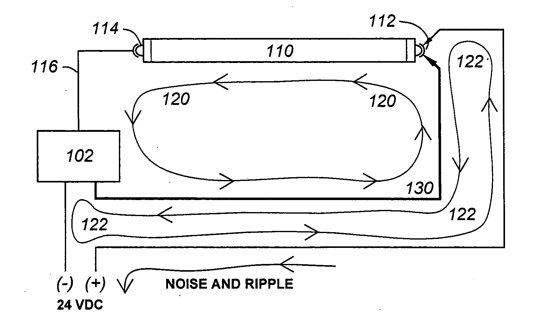
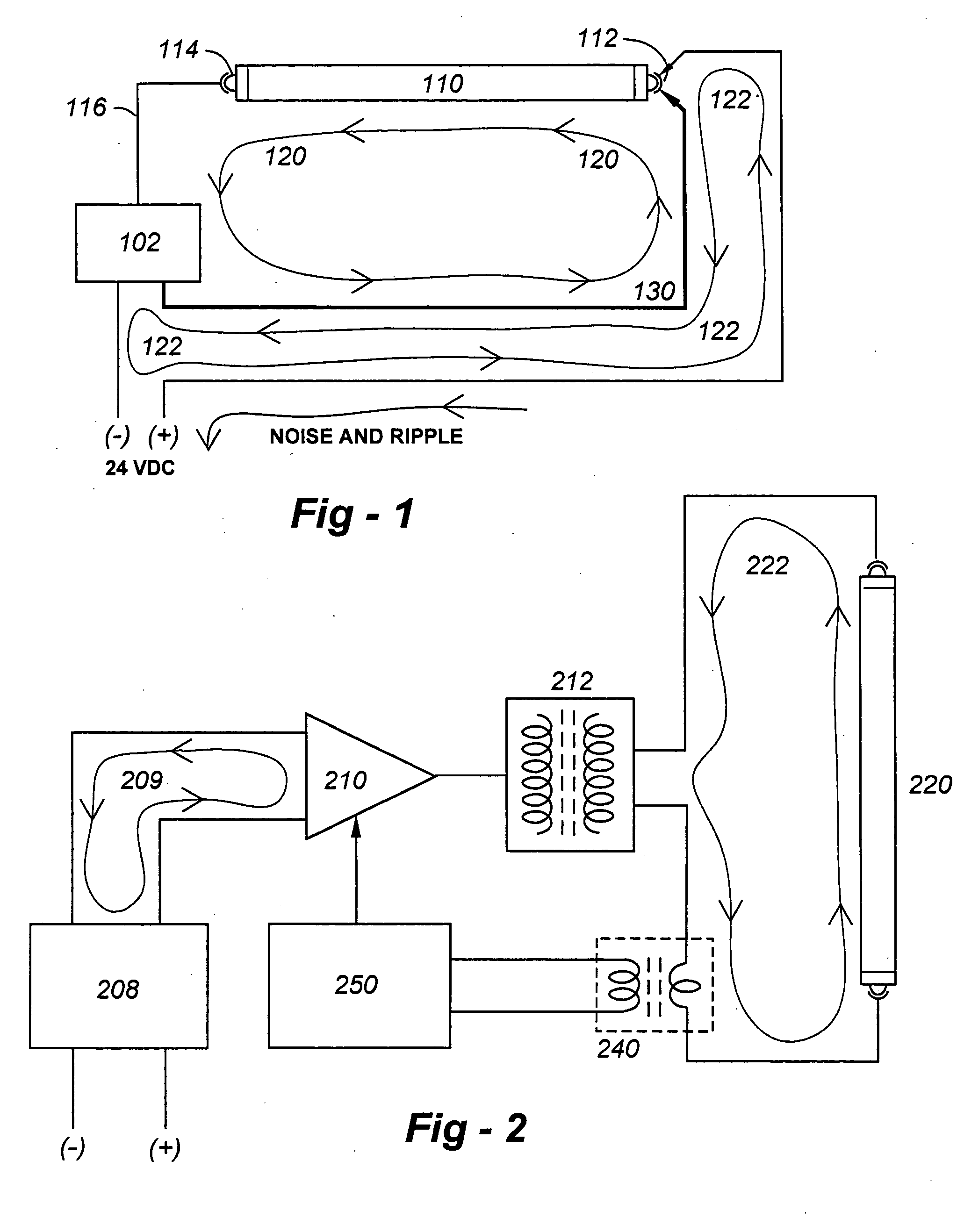
[0019] The system of this invention broadly prevents ripple and ballast-generated noise from feeding back into the buss power system of a lamp control circuit. This is broadly carried out by eliminating the common DC path and lamp current hook-up connection to the lamp. This is more particularly carried out by eliminating the safety switching action of the pin and the socket currently typical of single-pin systems.

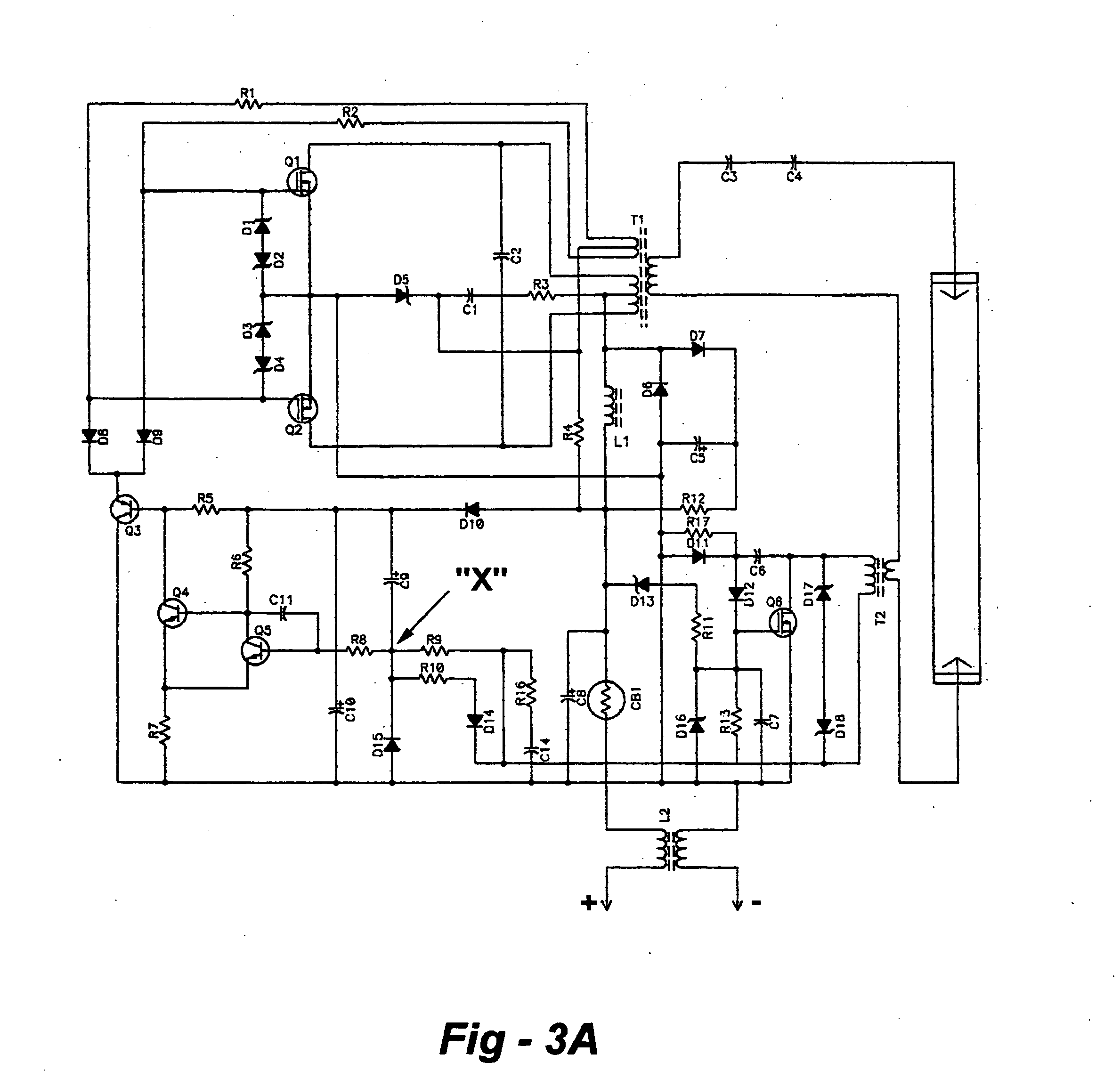
[0020] According to the invention, ballast shut down is performed electronically when the lamp is removed. The circuit of the invention detects the presence of the lamp current to keep the ballast running, but if the lamp is removed, the ballast shuts down to address safety issues. The invention further includes apparatus and methods to detect arcing that occur if a wire becomes loose, or if the socket is defective. In the preferred embodiment, the circuit detects arcing that lasts longer than a predetermined amount, such as 500 milliseconds, or thereabouts, and shuts dow...


PUM


Abstract

A shut-down circuit configured for use with an electronic ballast coupled to a lamp in a control path includes a device for sensing the electrical energy associated with the control path, and a sensing circuit for shutting down the ballast in the event that the energy does not conform to a predetermined condition. The sensed energy may be current indicative of lamp installation or removal, or voltage indicative of arcing. The device for sensing the electrical energy associated with the control path may be an isolation transformer or alternative devices such as optical isolators may be employed. The circuitry may further include electronic componentry to disable the sensing circuit during initial energization of the lamp. In one disclosed example, the sensing circuit includes a node that should be at or near a predetermined electrical potential when the lamp is operating properly, and a switch such as a Schmitt trigger coupled to the node that turns on or off to shut down the ballast if the node is not at or near the predetermined electrical potential. In an implementation used to detect voltage fluctuations indicative of arcing, the circuitry may include a high-pass filter or differentiator and detector to detect high-frequency noise. Alternatively, a phase-locked loop may be coupled to a low-pass filter to detect high-frequency noise indicative of arcing.

Description

FIELD OF THE INVENTION [0001] This invention relates generally to an electronic ballast and, in particular, to lamp-unseating and arc-detecting shut-down circuit and related improvements. BACKGROUND OF THE INVENTION [0002] Existing ballast circuits of the type used with fluorescent and, in some cases, neon lamps suffer from certain technical problems. Particularly with respect to single-pin lamps in DC-powered mobile applications, a single interconnection carries both DC input current and AC output current. This causes AC noise and ripple to feed back into the DC power buss distribution system, which, in turn, can affect performance and operation of other systems connected to the DC buss. [0003]FIG. 1 is a diagram of an existing single-pin lamp system. A 24-volt DC supply is connected to a ballast 102 and one side of the lamp 110. Typical of such systems, a safety switch 112 is provided to remove the DC power from the ballast if the lamp is removed. The connections are on either sid...

Claims


Application Information

Patent Timeline
Patent Type & Authority Applications(United States)
IPC IPC(8): H05B41/285
CPCH05B41/2855H05B41/2851Y10S315/07Y10S315/04
Inventor STACK, THOMAS
Owner Q TECH CO LTD
Why Eureka
Try Eureka