Switchless combining system and method

a technology of switching system and combining method, which is applied in the direction of coupling device, waveguide type device, basic electric element, etc., can solve the problems of high amplification ratio, high cost per unit power output, and inefficient tubes,

Inactive Publication Date: 2005-03-03
SPX CORP
View PDF5 Cites 60 Cited by
  • Summary
  • Abstract
  • Description
  • Claims
  • Application Information

AI Technical Summary

Benefits of technology

[0006] In one aspect, the invention provides a waveguide combiner for high-power radio signals, featuring a first orthogonal mode transducer (OMT) configured to accept RF from two driver circuits; a first polarization rotator, capable of adjusting the phase of each of the two RF signals from the first OMT; and a second OMT configured to couple energy impinging on its input ports into two output conductors.

Problems solved by technology

While tubes are not ideally efficient, they are practical, exhibiting very high amplification ratios, long life, toughness when misused, and low cost per unit power output when compared to current solid-state technologies.
Even amplifiers employing vacuum tubes have limited output power, however, and quickly become more costly if they use tubes that are individually capable of greater power output.
Since this failure mode behavior further degrades the working broadcast range of a transmitter system that has already lost half of its power, the alternative of being able to effectively return to half rather than a quarter of output power during a partial failure event can be significant.

Method used


Image

  • Switchless combining system and method
  • Switchless combining system and method
  • Switchless combining system and method

Examples


Embodiment Construction

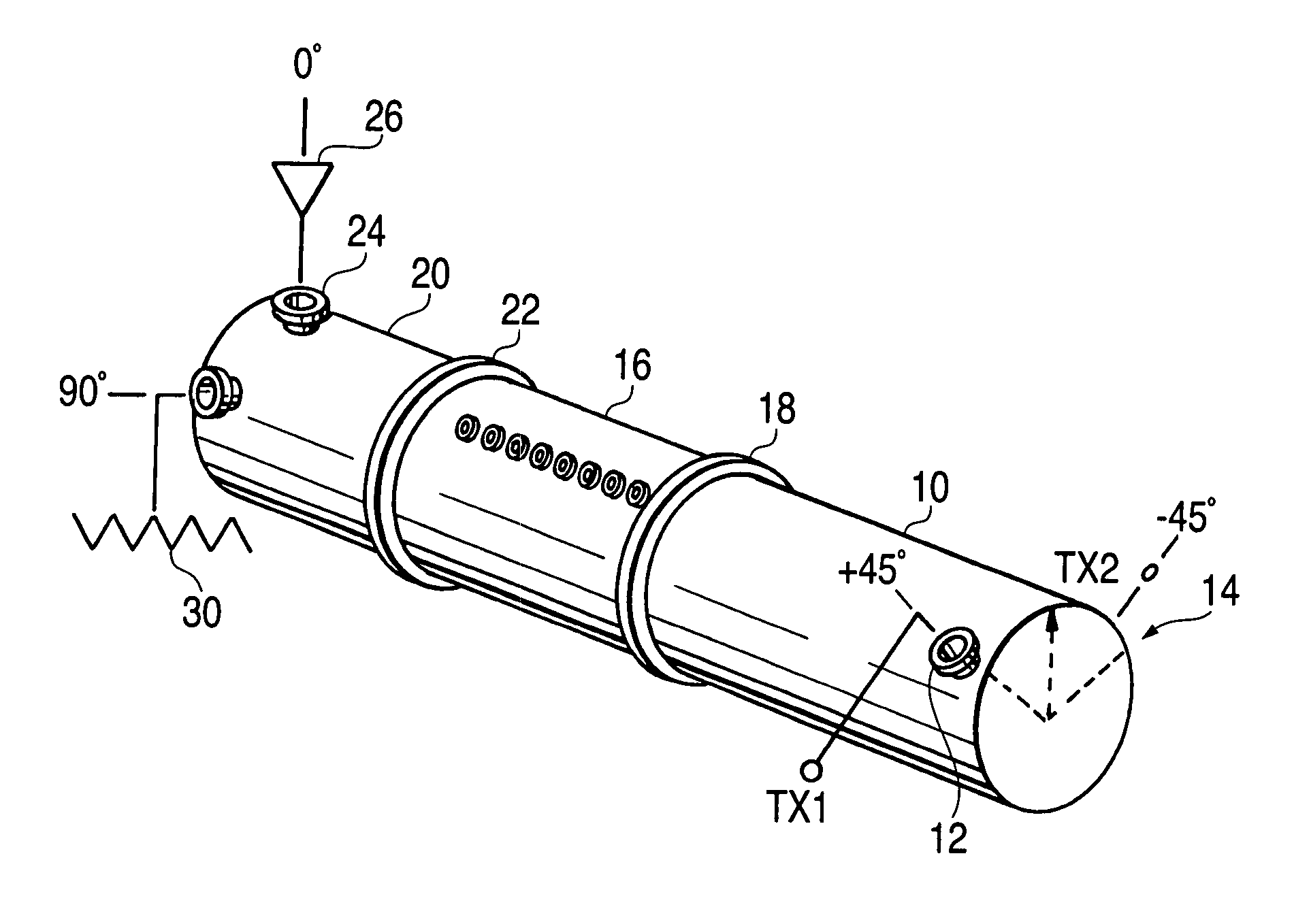
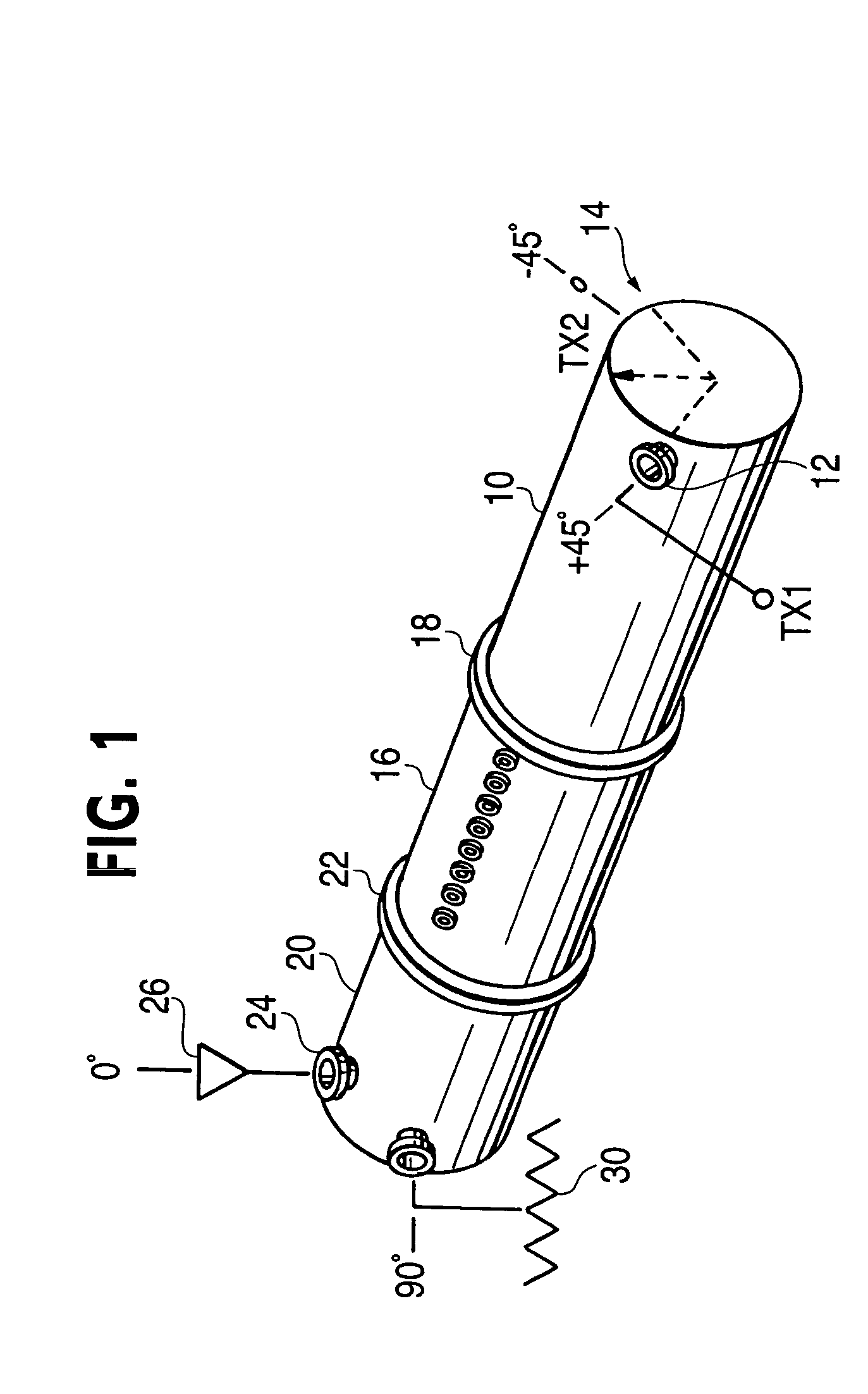
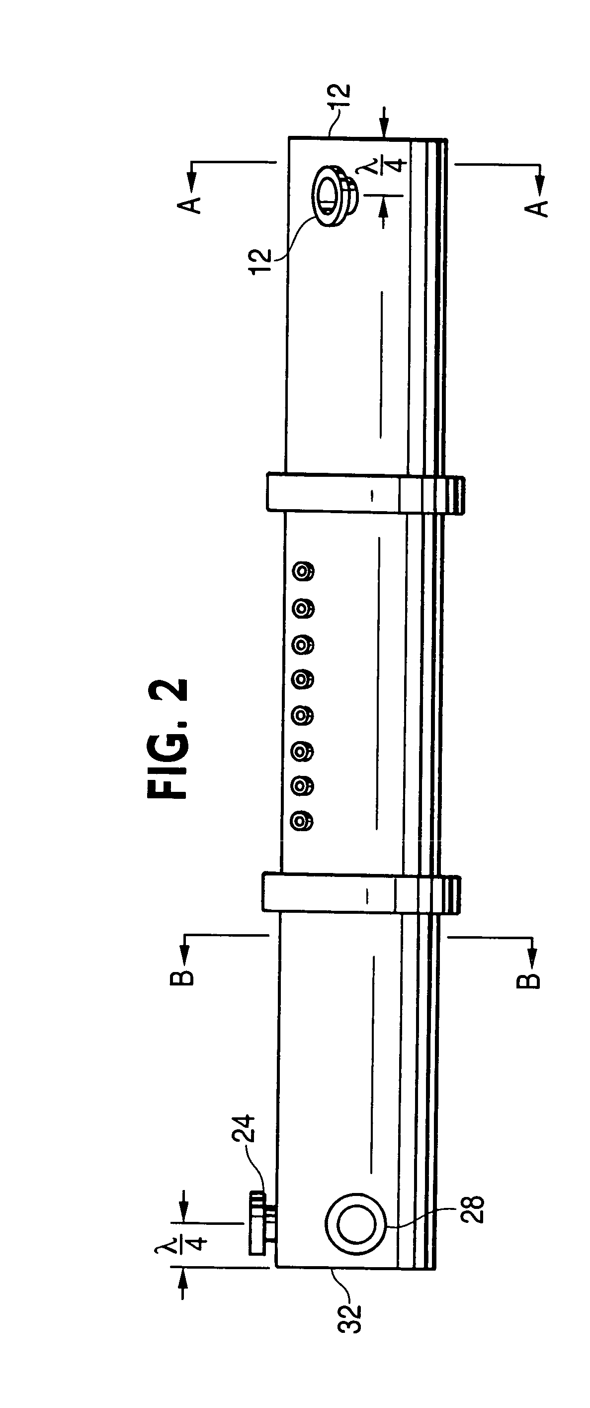
[0023] A preferred embodiment of a switchless combiner includes a first orthogonal-mode transducer (OMT), based on the concept of circular waveguide (CW), and functioning as an input device to feed signals from two coherent sources into the combiner. The switchless combiner further includes a circular waveguide polarizer functioning to cause the two source signals to combine or not according to its orientation. The third major element of the switchless combiner is a second circular waveguide OMT functioning as an output device to couple one or both signals to an antenna line or to a second output node.

[0024] Preferred embodiments of the invention will now be discussed with reference to the above figures, in which like reference numerals refer to like elements throughout. In accordance with a preferred embodiment of the present invention, the switchless combiner uses coaxial lines to feed all signals in and out of the circular waveguide chamber. FIGS. 1, 2, 4, and 5 illustrate this ...


PUM


Abstract

A switchless combiner for high-power broadcast signals incorporates a circular waveguide configured as an orthogonal mode transducer to provide a coherent signal and a phase rotator to steer the combined signal to an output coupler. Out-of-phase RF is absorbed by a station load. The phase rotator is capable of redirecting the output from either of the sources or all of the combined output to the station load. Switching between destinations for the RF components may be made with power applied. The input and output characteristics and mechanical configuration permit the switchless combiner to be integrated with other high-power RF broadcast signal manipulation devices.

Description

FIELD OF THE INVENTION [0001] The present invention relates generally to high power radio frequency transmission (RF). More particularly, the present invention relates to systems and methods that combine the outputs of multiple high-power radio frequency amplifiers into a single coherent signal for broadcast on a single antenna system. BACKGROUND OF THE INVENTION [0002] A basic radio frequency transmitter can use a low-level signal ready for transmission and boost it using successive stages of amplification until the level is high enough (from 25 kilowatts (KW) to 240 KW or more) to be suitable for television broadcasting or another high-power use, such as particle physics research. [0003] Extreme-power amplification often uses vacuum tubes. While tubes are not ideally efficient, they are practical, exhibiting very high amplification ratios, long life, toughness when misused, and low cost per unit power output when compared to current solid-state technologies. Even amplifiers employ...

Claims


Application Information

Patent Timeline
Patent Type & Authority Applications(United States)
IPC IPC(8): H01P5/04
CPCH01P5/04
Inventor STENBERG, JAMES
Owner SPX CORP
Why Eureka
Try Eureka