Display apparatus, image processing apparatus, and image processing system

a technology of image processing and display apparatus, applied in the field of display apparatus, image processing apparatus, and image processing system, can solve the problems of inability to see inability to find the portion with the largest change amount from accumulated images, and inability to detect invaders at a high probability

Active Publication Date: 2005-03-03
CANON KK
View PDF5 Cites 110 Cited by
  • Summary
  • Abstract
  • Description
  • Claims
  • Application Information

AI Technical Summary

Benefits of technology

It is the first object of the present invention to make it possible to display time progress of the change amount in an image and displ...

Problems solved by technology

If the magnitude of the change amount between the displayed images is unknown, as described above, it is difficult to find the portion with the largest change amount from accumulated images.
Hence, it may be impossible at a high probability to see desired images after image accumulation.
If the detection sensitivity is too low, no invaders can be detected.
Conversely, if the sensitivity setting is too high, notification takes place even when it is unnecessary.
In systems of...

Method used


Image

  • Display apparatus, image processing apparatus, and image processing system
  • Display apparatus, image processing apparatus, and image processing system
  • Display apparatus, image processing apparatus, and image processing system

Examples


first embodiment

In the first embodiment, an image change detection system will be described, in which a change in photographed image is detected in a camera server, and a graph representing a time-series change in consequently accumulated change detection amount and the image at the time of change detection are displayed on the screen of an image change detection setting client (to be simply referred to as a setting client hereinafter).

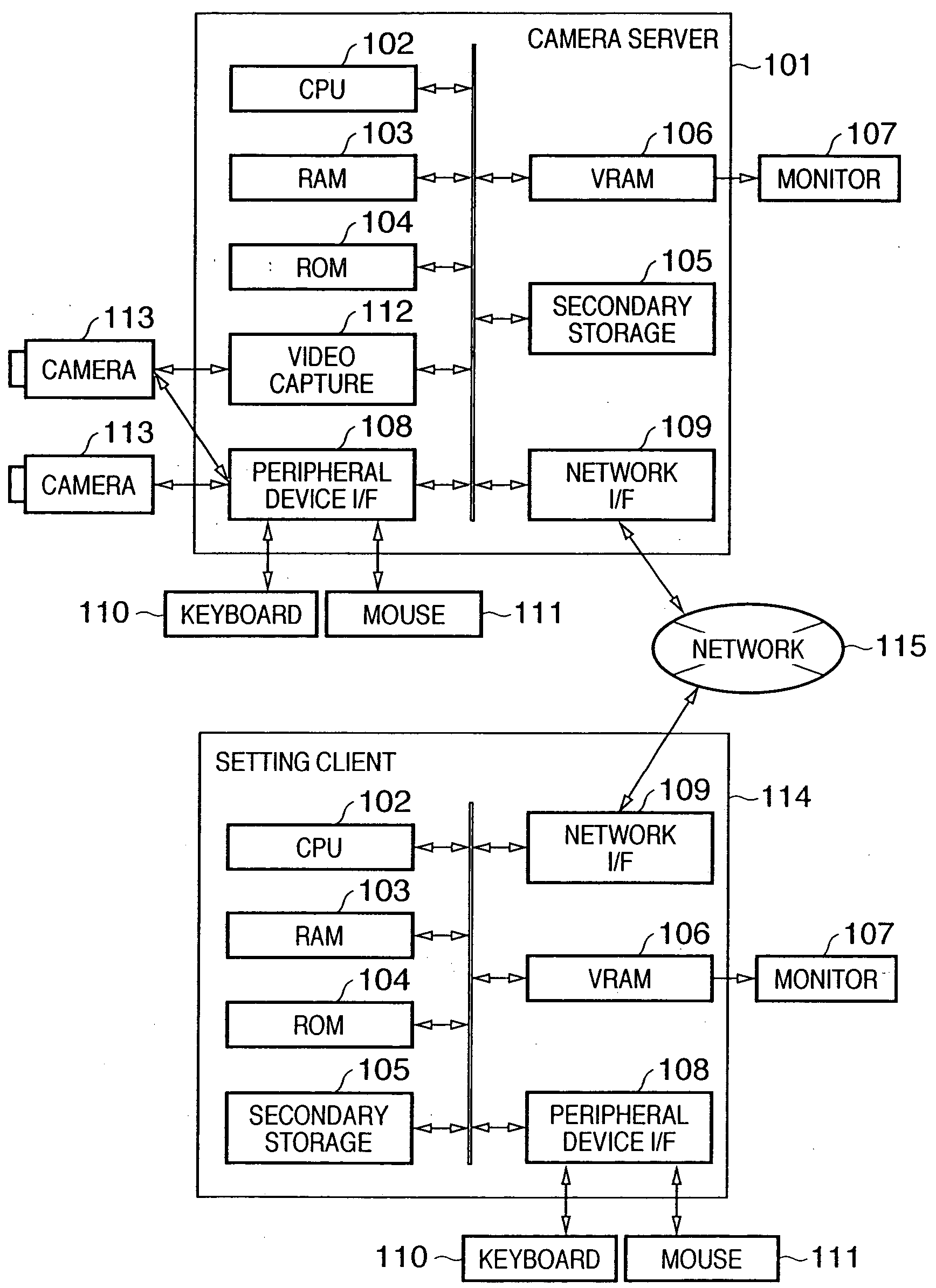
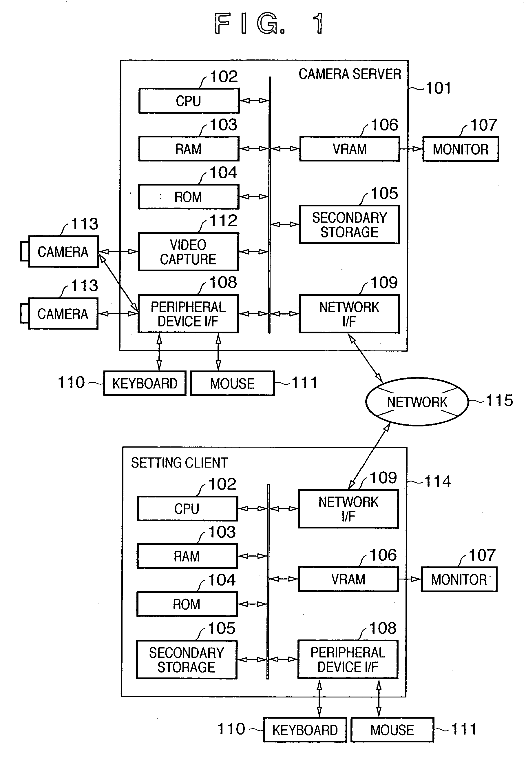
FIG. 1 is a block diagram showing the hardware configuration of the image change detection system according to this embodiment. The image change detection system according to this embodiment includes a camera server 101 and a setting client 114, which are connected through a network 115.

The camera server 101 acquires an image photographed by a camera 113 and transmits the image to the setting client 114 through the network 115. In addition, image change detection processing is executed in the camera server and accumulates the image at the time of change detection...

second embodiment

The second embodiment is different from the first embodiment in the motion detection log display window. FIG. 10 is a view showing the motion detection log display window according to the

In this embodiment, as shown in FIG. 10, in a log display portion 1002 which displays a change log in a window 1001 displayed on the monitor of a setting client, a plurality of kinds of symbols are used in accordance with the image accumulation timing as symbols representing accumulated images at the time of change detection, which are displayed in relation to a graph 1004. In the illustrated example, an image at the start of change detection is represented by a symbol 1005. An image during change detection is represented by a symbol 1006. An image at the end of change detection is represented by a symbol 1007. The symbols have different shapes. Accordingly, the start or end timing of change detection can more visually be expressed. The number of kinds of symbols to be used is not limited to three....

third embodiment

The third embodiment of the present invention will be described below. In the third embodiment, an image change detection system similar to those of the first and second embodiments will be described. A description of the same parts as in the above embodiments will be omitted. Characteristic parts of the third embodiment will mainly be described.

In the third embodiment, symbols representing accumulated images at the time of motion detection are displayed as a set in each period when the motion amount is continuously not less than the threshold value. FIG. 11 is a view showing a motion detection log display window according to the third embodiment.

As shown in FIG. 11, in this embodiment, in a log display portion 1102 which displays a change log in a window 1101 displayed on the monitor of a setting client, symbols representing accumulated images at the time of change detection, which are displayed in relation to a graph 1104, are displayed in the same color or pattern (design) i...


PUM


Abstract

In a display apparatus connected to an image processing apparatus which detects the change amount in an input image and stores, as a detected image, an image during a period with a change amount equal to or more than a predetermined amount, the change log of the change amount and the detected image are received, the change log is displayed by using a graph, and information related to the detected image is displayed on the graph in a superposed manner.

Description

FIELD OF THE INVENTION The present invention relates to a display apparatus, image processing apparatus, and image processing system and, more particularly, to a technique for storing an image when an image change amount not less than a predetermined amount is detected in a monitoring system or camera server. The present invention also relates to an image processing apparatus and method for an image photographed by a camera and, more particularly, to setting of motion detection sensitivity. The present invention also relates to an image motion detection method and apparatus for detecting motion of a moving image, and a program and storage medium thereof. BACKGROUND OF THE INVENTION In monitoring systems which photograph a moving image by using a camera, a technique for automatically detecting a change (scene change) in a photographed moving image by image processing and saving / accumulating (storing) the image when the change is detected has been put into practical use. In such ...

Claims


Application Information

Patent Timeline
IPC IPC(8): G08B13/194G11B27/034G11B27/10G11B27/28G11B27/30G11B27/34H04N5/225H04N5/76H04N5/765H04N5/77H04N5/775H04N7/18H04N9/804
CPCG08B13/19602H04N7/18G08B13/19667G08B13/19669G08B13/19671G08B13/19676G08B13/1968G08B13/19682G08B13/19691G11B27/034G11B27/105G11B27/28G11B27/3045G11B27/34H04N5/76H04N5/765H04N5/77H04N5/775H04N7/181H04N9/8042H04N9/8047G06T7/20G08B13/19604
Inventor OYA, TAKASHIFUKUSAWA, TOSHIHIKO
Owner CANON KK
Why Eureka
Try Eureka