Device and method for performing multiple view imaging by means of a plurality of video processing devices

a video processing device and multiple view technology, applied in the field of multiple view image display, can solve the problems of poor stereo performance, flickering images, and the power of the igs generating images for both eyes at 48 hz or more, and achieve the effect of reducing latency

Active Publication Date: 2005-03-03
BARCO NV
View PDF17 Cites 87 Cited by
  • Summary
  • Abstract
  • Description
  • Claims
  • Application Information

AI Technical Summary

Benefits of technology

[0027] The output control signal, e.g. stereo control signal, may be functionally compatible with the linking signal, thus eliminating the need for both separate signals.
[0039] An imaging system according to the present invention may be adapted to reduce latency between a pair of image frames of the first sequence of image frames and a subsequent output of a corresponding pair of image frames of the fourth sequence by starting the output of a first multiple view display image frame of the pair of display image frames of the fourth sequence before arrival of the complete pair of image frames of the first sequence of image frames when it is known that the completion of the arrival will occur before the expected completion of the output of the first multiple view display image frame of the fourth sequence.
[0048] The method may furthermore comprise generating a control signal for an image modulation device, such as shutter glasses or an LCD panel such as a Z-screen, allowing the image modulation device to properly synchronise with a output rate and phase of the fourth sequence of image frames.
[0049] The processing of image frames of the first sequence may be optimised to reduce latency between a pair of image frames of the first sequence and a subsequent output of a corresponding pair of image frames of the fourth sequence by starting the output of a first multiple view display image frame of the fourth sequence before arrival of the complete pair of image frames of the first sequence when it is known that the completion of the arrival will occur before the expected completion of the output of the first multiple view display image frame of the fourth sequence.

Problems solved by technology

Furthermore IGs generating images for both eyes each at 48 Hz or more have to be powerful, and thus are expensive.
However, displaying these images at these lower frequencies would certainly result in flickering images, and is thus not desirable.
Therefore, in a multiple projector system, the stereo performance will be poor as each projector creates its own refresh rate that is not synchronised with the others and, for active stereo systems, with the control signal of the shutter glasses.
Implementing the emitter phasing logic as in the set-up of FIG. 2 cannot overcome the differences between these images and the emitter control signal.

Method used


Image

  • Device and method for performing multiple view imaging by means of a plurality of video processing devices
  • Device and method for performing multiple view imaging by means of a plurality of video processing devices
  • Device and method for performing multiple view imaging by means of a plurality of video processing devices

Examples


Embodiment Construction

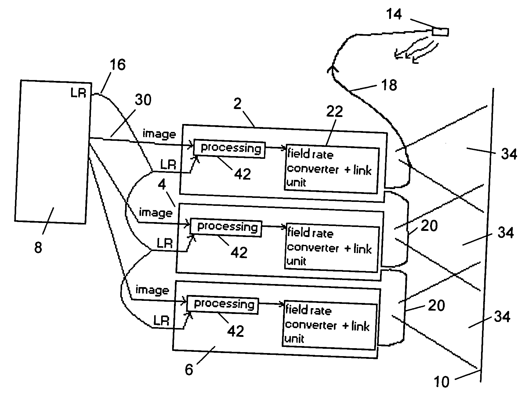
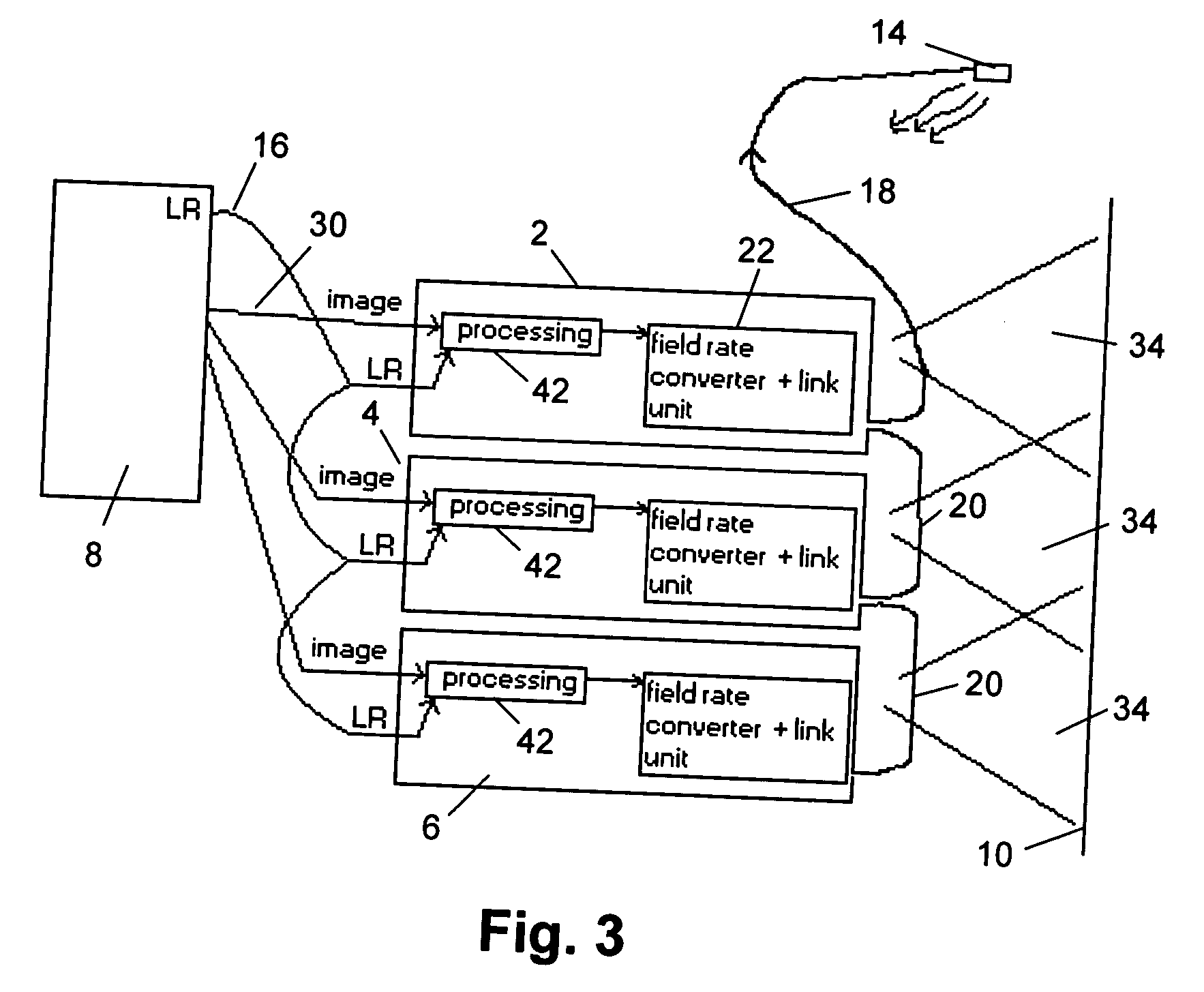
[0060] The present invention will be described with respect to particular embodiments and with reference to certain drawings but the invention is not limited thereto but only by the claims. In particular the detailed description of the present invention refers to stereoscopic imaging, but it is not intended to limit the invention thereto. The invention also covers “multiple view display” in the sense of images being divided between observers looking from different locations in a room at the same screen or different screens onto which images are being displayed.

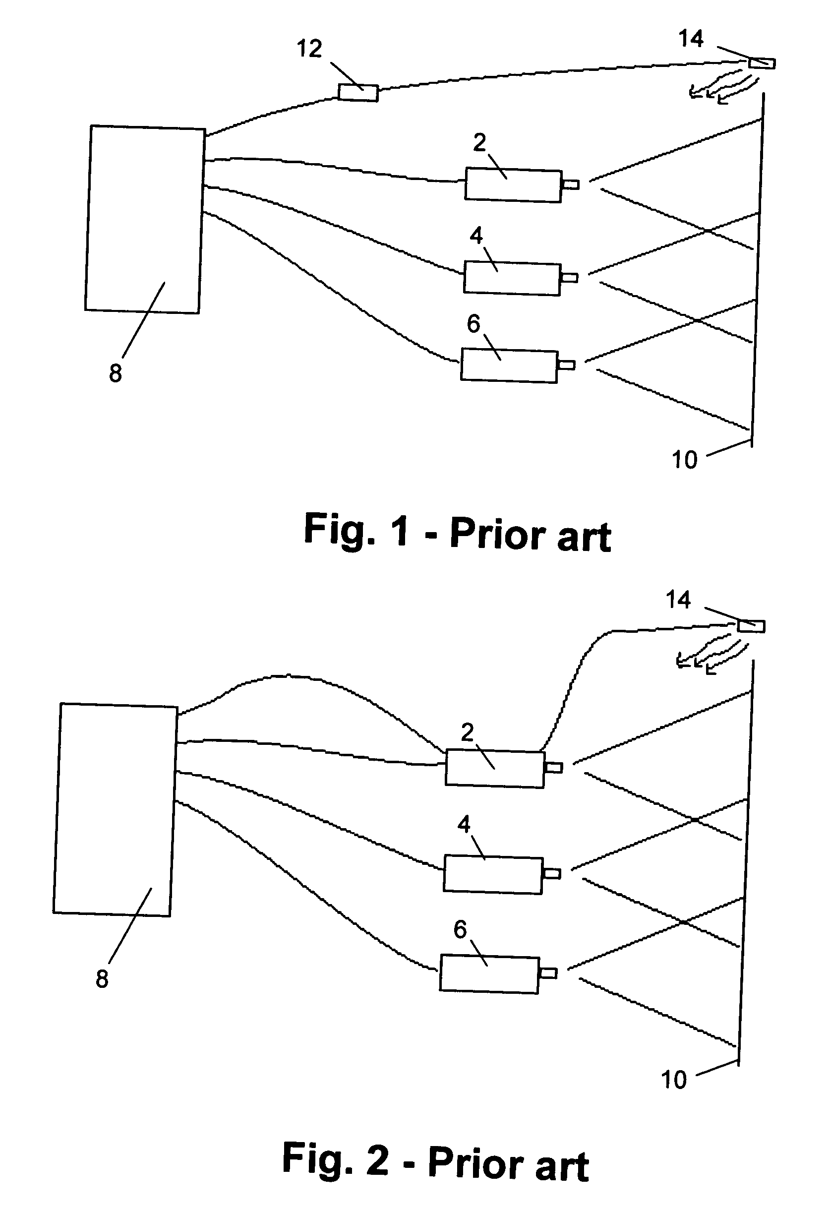
[0061] The drawings described are only schematic and are non-limiting. In the drawings, the size of some of the elements may be exaggerated and not drawn on scale for illustrative purposes.

[0062] The term “video” as used in this invention should be interpreted broadly. It includes not only sequences of video frames which are in accordance with a known television, multimedia or other display format but also any sequence of fr...


PUM


Abstract

In one aspect, the present invention provides an imaging system for multiple view imaging. Multiple view imaging comprises, but is not limited to, stereoscopic imaging. The imaging system for multiple view imaging comprises at least two video processing devices, each of the video processing devices being for displaying a video image on one or more display devices. Each video processing device receives at least a first sequence of image frames comprising at least second sequence of image frames and a third sequence of image frames, the at least second and third sequences being for generating at least first and second video images, respectively. Each video processing device outputs at least a fourth sequence of image frames, the fourth sequences being for generating at least one of the first or second video images, the fourth sequences of image frames from the first and second video processing devices being asynchronous with respect to each other. The imaging system is adapted to generate a linking signal for synchronising images displayed by the at least first and second video processing devices on the one or more display devices. In other aspects, the present invention provides a method for performing multiple view imaging by means of at least two video processing devices, and a controller for controlling the operation of at least two video processing devices in an imaging system for displaying multiple view images.

Description

TECHNICAL FIELD OF THE INVENTION [0001] The present invention relates to methods and apparatus for multiple view image display, such as e.g. stereoscopic image display, for example stereoscopic projection or image display for being viewed by different persons from different locations, more particularly to multiple view image display by means of a plurality of video processing devices or channels as well as control methods and controllers therefor. BACKGROUND OF THE INVENTION [0002] Humans and many animals have binocular vision provided by two eyes which look in the same direction. Two parallel aligned but spaced eyes deliver two slightly different images of the same scene. This is due to the 4 to 6 cm separation between the eyes, which makes each eye have a slightly different viewpoint. The images from these two different viewpoints are sent to the brain, and this difference, which is termed parallax, is interpreted as depth. The nearer an object is to the eyes, the greater the diff...

Claims


Application Information

Patent Timeline
Patent Type & Authority Applications(United States)
IPC IPC(8): H04N13/00
CPCH04N13/0497H04N13/0029H04N13/139H04N13/398
Inventor BRACKE, IVE
Owner BARCO NV
Why Eureka
Try Eureka