
Vehicle accessory module

a technology for accessories and vehicles, applied in the field of accessories, can solve the problems of difficulty for automobile assembly-line operators to mount such accessories, and achieve the effects of convenient installation, enhanced assembly or installation process, and convenient installation

Inactive Publication Date: 2005-03-03
MAGNA ELECTRONICS
View PDF5 Cites 67 Cited by
  • Summary
  • Abstract
  • Description
  • Claims
  • Application Information

AI Technical Summary

Benefits of technology

The present invention provides an accessory module that can be easily mounted on the windshield of a vehicle. The module has a mounting portion that attaches to the windshield and a head portion that extends above the windshield. The head portion contains electronic circuitry for various accessories, such as a rain sensor, temperature sensor, image sensor, and more. The accessory module can be movable and articulatable to adjust its angle with respect to the driver of the vehicle. The accessory system also includes an interior rearview mirror assembly that can be mounted on the second attachment member of the accessory module. The invention provides an improved accessory system that allows for easy installation and adjustable positioning of accessories on the vehicle windshield.

Problems solved by technology

It may be difficult for automobile assembly-line operators to mount such accessories onto, for example, a mirror mounting button on the interior surface of the windshield of a vehicle being assembled, since the assembly processes require multiple operations at the vehicle assembly plant.

Method used


Image

  • Vehicle accessory module
  • Vehicle accessory module
  • Vehicle accessory module

Examples


Embodiment Construction

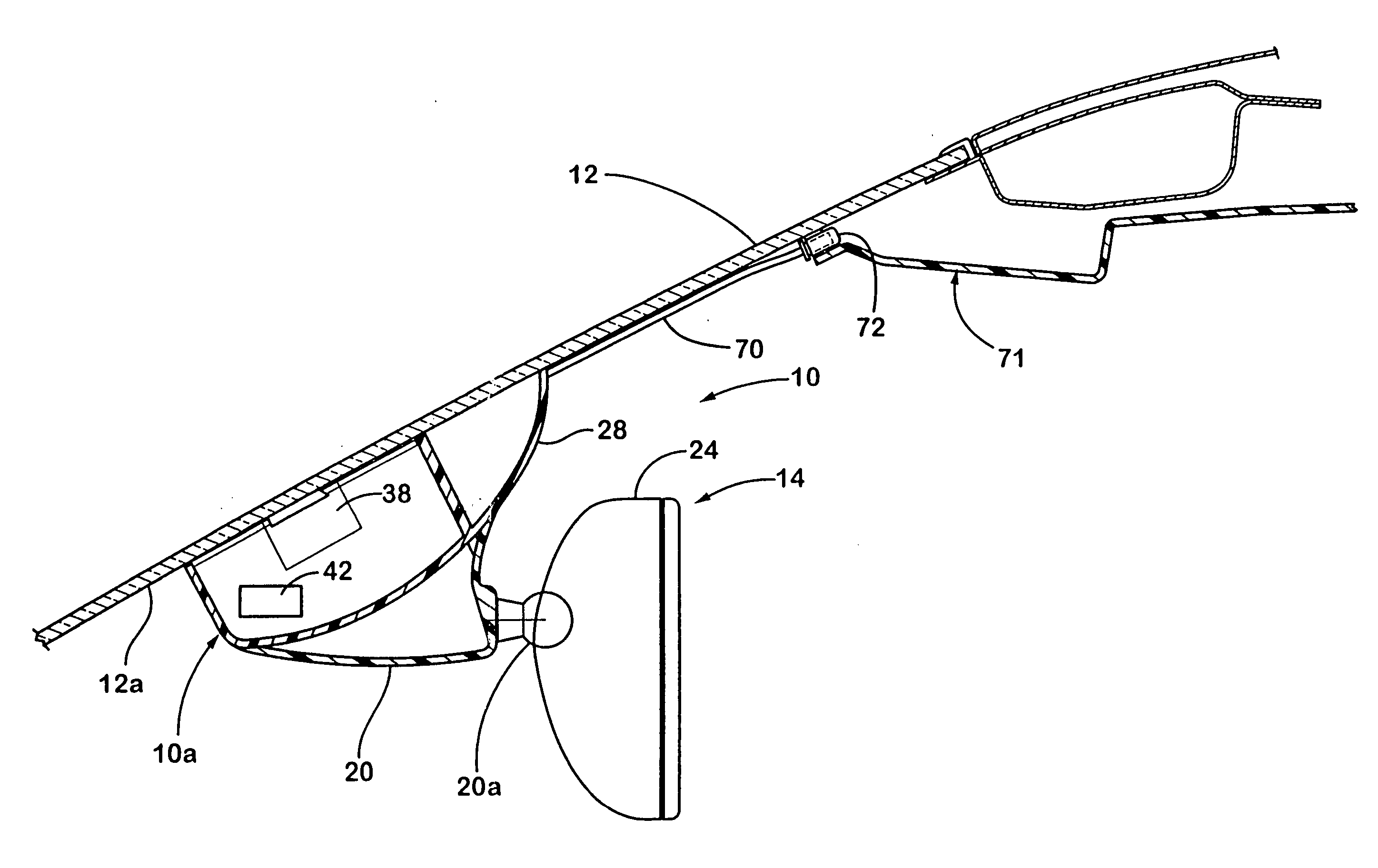
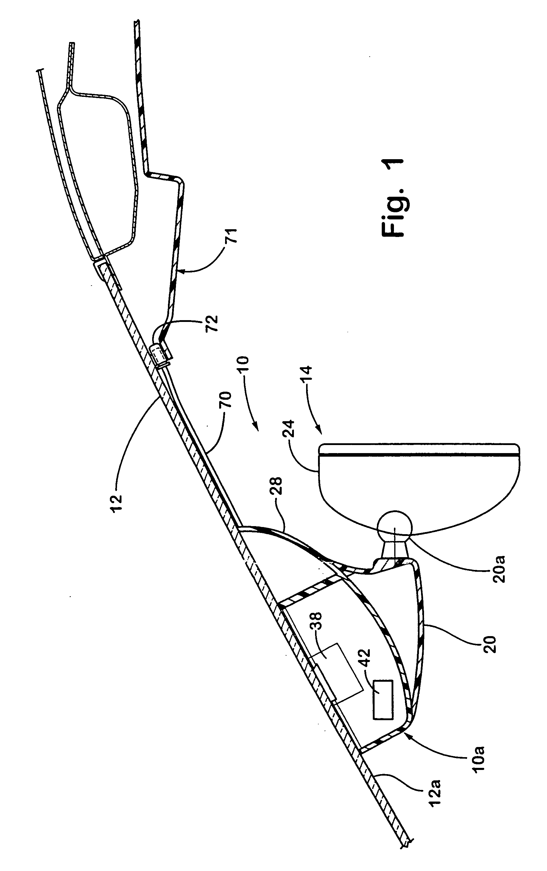
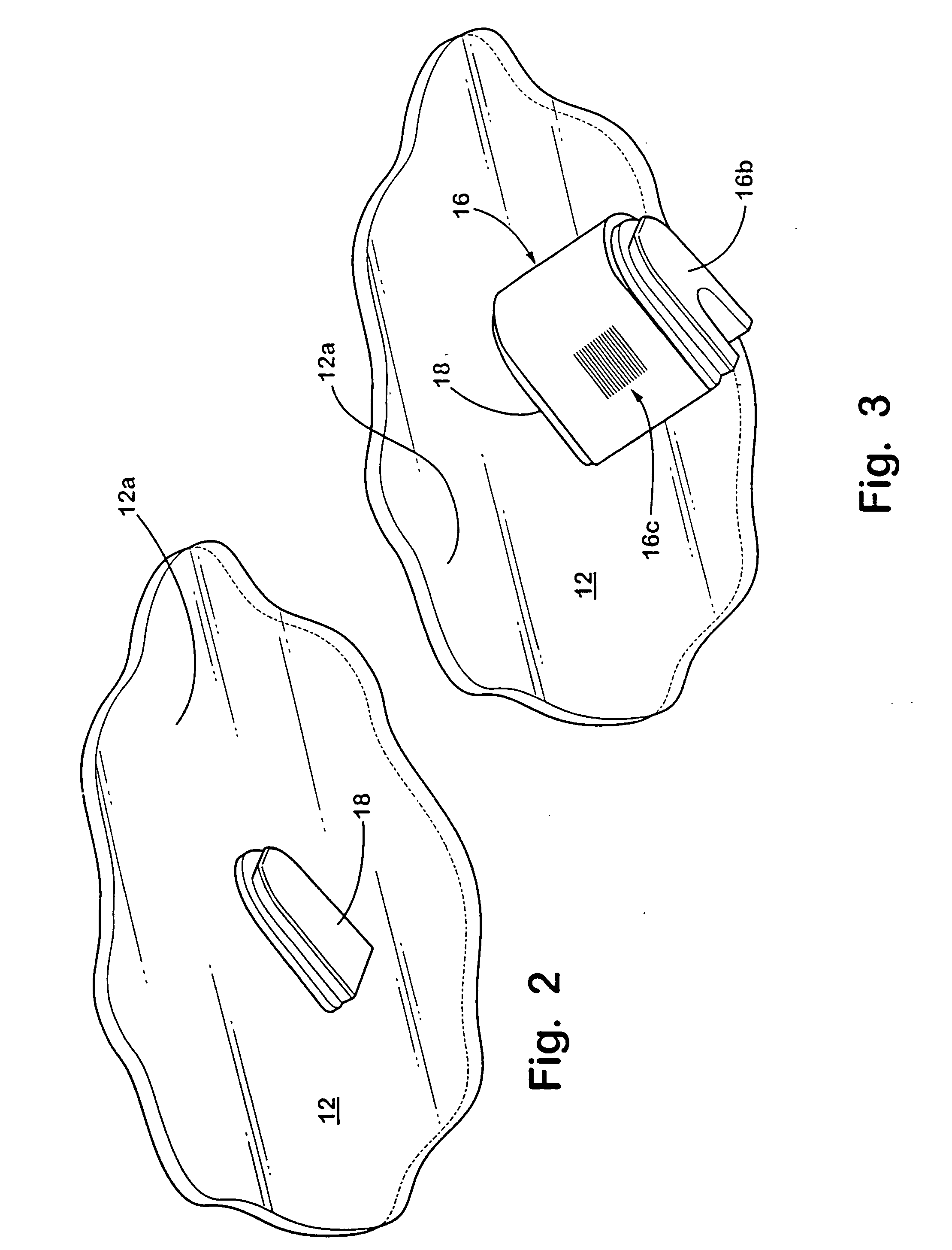
[0102] Referring now to the drawings and the illustrative embodiments depicted therein, an accessory module 10 is mountable to and against a windshield 12 and is positioned generally between an interior rearview mirror assembly 14 and the windshield 12 (FIGS. 1 and 5-10). The accessory module 10 is mounted toward and against an interior surface 12a of the windshield in a manner which allows the body 10a of the accessory module to move generally perpendicularly relative to the interior surface 12a and to be loaded against or biased toward and to the windshield, as discussed in detail below, and such as disclosed in commonly assigned U.S. provisional applications, Ser. No. 60 / 381,314, filed May 17, 2002 by Schofield et al. for VEHICLE ACCESSORY MODULE (Attorney Docket DON01 P-989); Ser. No. 60 / 374,724, filed Apr. 23, 2002 by Schofield et al. for VEHICLE ACCESSORY MODULE (Attorney Docket DON01 P-975); Ser. No. 60 / 364,008, filed Mar. 14, 2002 by Schofield for VEHICLE ACCESSORY MODULE (A...


PUM


Abstract

An accessory system of a vehicle comprises an accessory module assembly having a mounting portion, a head portion and a rearview mirror assembly. The mounting portion extends generally upward when mounted to an attachment member at a vehicle windshield. The head portion may extend generally horizontally and rearwardly with respect to the vehicle from an upper portion of the mounting portion. The head portion comprises electronic circuitry for at least one accessory. The mirror assembly is mountable to the mounting portion, with the head portion of the accessory module assembly extending generally above the mirror casing. The head portion may be viewable and / or user accessible above the mirror casing when the mirror assembly is mounted to the mounting portion. The head portion may be pivotable or articulatable relative to the base portion of the accessory module assembly.

Description

CROSS-REFERENCE TO RELATED APPLICATIONS [0001] The present application claims priority of U.S. provisional applications, Ser. No. 60 / 420,560, filed Oct. 23, 2002 (Attorney Docket DON01 P-1046); Ser. No. 60 / 398,346, filed Jul. 24, 2002 (Attorney Docket DON01 P-1014); Ser. No. 60 / 381,314, filed May 17, 2002 (Attorney Docket DON01 P-989); Ser. No. 60 / 374,724, filed Apr. 23, 2002 (Attorney Docket DON01 P-975); Ser. No. 60 / 364,008, filed Mar. 14, 2002 (Attorney Docket DON01 P-967); and Ser. No. 60 / 350,965, filed Jan. 31, 2002 (Attorney Docket DON01 P-964), which are all hereby incorporated herein by reference in their entireties.FIELD OF THE INVENTION [0002] The present invention relates generally to accessories useful for a vehicle and, more particularly, to accessories used in windshield electronic modules and interior rearview mirror assemblies. BACKGROUND OF THE INVENTION [0003] Certain accessories of a vehicle, such as a rain sensor or imaging sensor, typically are mounted tight aga...

Claims


Application Information

Patent Timeline
Patent Type & Authority Applications(United States)
IPC IPC(8): B60R1/04B60R1/12
CPCB60R1/04B60R1/12B60R1/1207B60R11/04B60R2001/1215B60R2001/1223B60R2001/123B60R2001/1246B60R2001/1253B60R2001/1261B60R2001/1276B60R2001/1284H04N7/18H04N23/698H04N25/76B60R1/10B60R2300/106B60R2300/108B60R2300/8033H04N7/183
Inventor SCHOFIELD, KENNETHDEWARD, JOSHUAWHITEHEAD, PETERLYNAM, NIALL
Owner MAGNA ELECTRONICS
Learn More