Cable drive system

a drive system and cable technology, applied in the direction of shafts for rotary movement, fastening means, couplings, etc., can solve the problems of generating noise and chatter between the cable end and the drive shaft, prone to breakage, and inconvenient stamping of metal stock, so as to reduce the difficulty and expense of manufacturing the present drive system. , the effect of reducing the waste of metal stock

Inactive Publication Date: 2005-03-03
FASCO IND INC
View PDF12 Cites 3 Cited by
  • Summary
  • Abstract
  • Description
  • Claims
  • Application Information

AI Technical Summary

Benefits of technology

[0014] Advantageously, the driving engagement of the drive clip arms and the circular bore of the drive shaft provides a driving connection between the drive shaft and the cable end portion while eliminating the need of a broaching operation to form a square or other polygonal shaped hole in the end of the drive shaft which conforms to the shape of the cable end portion. In this manner, the difficulty and expense of manufacturing the present drive system is greatly reduced as compared to known drive systems. Additionally, using multiple drive clips of the shape described herein allows the drive clips to be economically formed from metal stock by a stamping operation in which waste of metal stock is greatly reduced.

Problems solved by technology

Problematically, any spacing or gaps between the flexible cable end and the motor drive shaft due to manufacturing tolerances, for example, may lead to the generation of noise and chatter between the cable end and drive shaft during operation of the drive system.
However, due to the cross shape of the stamped blank of spacer 12, stamping same from a sheet of metal stock is not economical because a large amount of the metal stock is wasted.
Another disadvantage of the foregoing drive system is that the broaching operation needed to form the square or other polygonal shape of hole 14 of drive shaft 16 is a relatively difficult manufacturing step which requires tooling that must be periodically sharpened or replaced, and which is prone to breakage.
Further, the broaching operation is expensive, and performance of same could disrupt or damage the outer diameter of the drive shaft.

Method used


Image

  • Cable drive system
  • Cable drive system
  • Cable drive system

Examples


Embodiment Construction

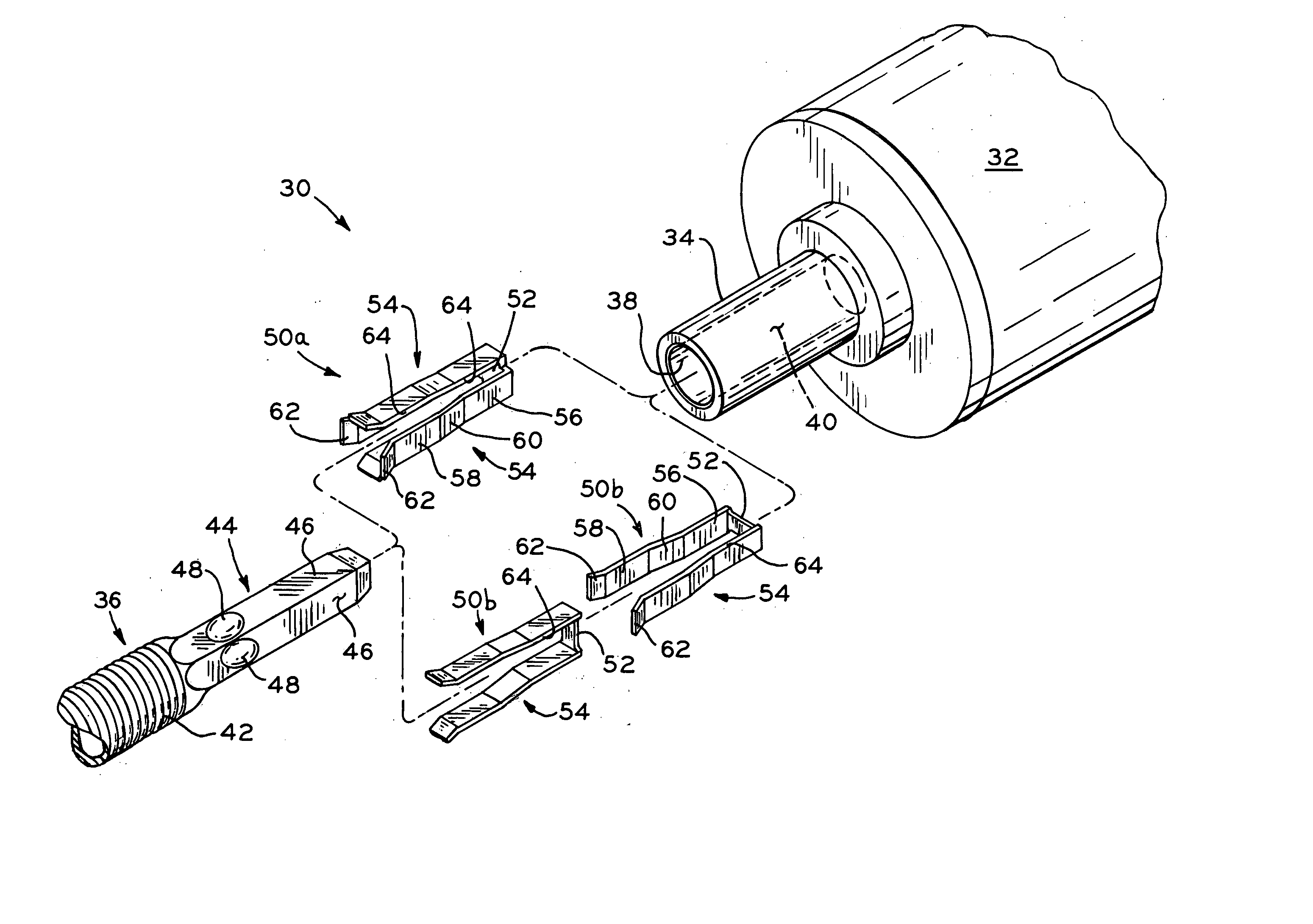
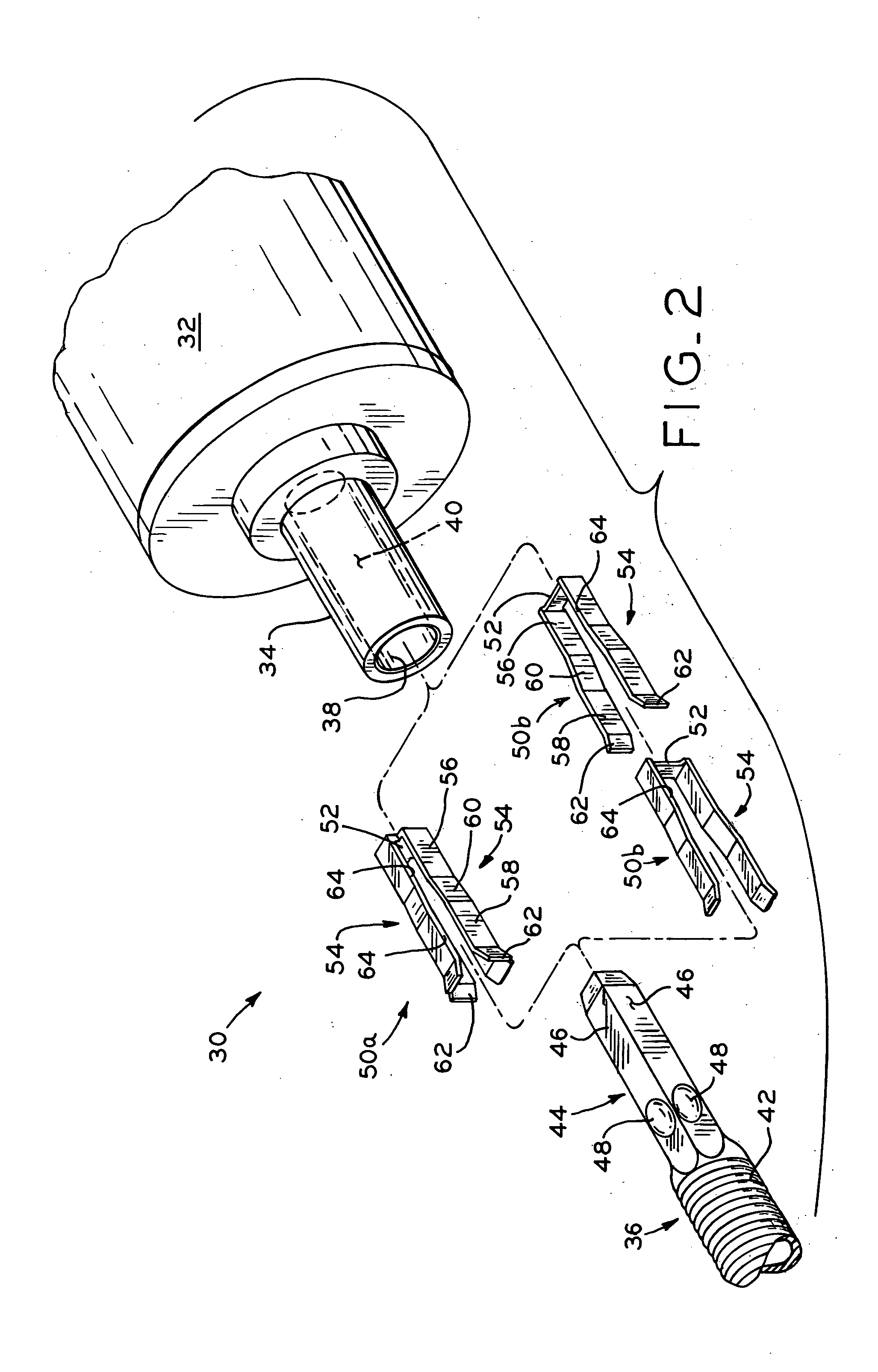
[0028] Referring to FIG. 2, the components of drive system 30 according to the present invention are shown. Drive system 30 includes a prime mover or rotary motion source, shown herein as electric motor 32 having rotatable drive shaft 34. Drive shaft 34 is coupled to flexible cable 36 to provide a driving connection therebetween for transmitting rotary power or torque from drive shaft 34 of motor 32 through flexible cable 36 to a gear box or other driven device (not shown).

[0029] Although drive system 30 is described herein in the exemplary form of a driving connection between an electric motor and a flexible cable, the present invention is also more generally applicable to other types of drive systems in which rotary motion is transferred from any type of drive component to any type of driven component such as an axle or rigid shaft, for example, or other driving connections including solid links. Additionally, although the present invention is described below with reference to ex...


PUM


Abstract

A drive system for drivingly coupling two components to one another, for example, a drive shaft and a driven component such as a flexible cable. The end of the drive shaft is formed with a circular bore, and the end of the flexible cable is formed with a square or other polygonal shape. One or more drive clips within the cylindrical bore drivingly engage the inner surface of the circular bore of the drive shaft, and also conform to the external surfaces of the cable end portion to prevent relative rotation between the drive shaft and the flexible cable, such that same are drivingly coupled.

Description

CROSS REFERENCE TO RELATED APPLICATIONS [0001] This application claims the benefit under Title 35, U.S.C. § 119(e) of U.S. Provisional Patent Application Ser. No. 60 / 499,107, entitled CABLE DRIVE SYSTEM, filed on Aug. 29, 2003.BACKGROUND OF THE INVENTION [0002] 1. Field of the Invention [0003] The present invention relates to drive systems for transferring rotary motion from a drive component to a driven component such as, for example, a drive system in which a flexible cable is driven by an electric motor. [0004] 2. Description of the Related Art [0005] Generally, drive systems are used to transfer rotary motion or torque between two components, such as from a drive component to a driven component. For example, a source of rotary motion, such as an electric motor, internal combustion engine, or other power source may be used to drive a rotary device. In some drive systems, a flexible cable is used to transfer rotary motion from a source of rotary motion to a driven device. [0006] I...

Claims


Application Information

Patent Timeline
Patent Type & Authority Applications(United States)
IPC IPC(8): F16C1/08F16D1/108
CPCF16C1/08Y10T403/60F16D1/108F16D2001/102
Inventor ALLSWEDE, STEPHEN W.
Owner FASCO IND INC
Why Eureka
Try Eureka