Implant for fixing bone plates

Inactive Publication Date: 2005-03-03
AESCULAP AG
View PDF50 Cites 15 Cited by
  • Summary
  • Abstract
  • Description
  • Claims
  • Application Information

AI Technical Summary

Benefits of technology

[0007] In accordance with an example embodiment of the invention, an implant is provided for fixing neighbouring bone plates of the cranial bone in a simple and reliable manner. The bone plates each have an inner surface and an outer surface. The implant comprises an outer bearing element for covering a spacing gap between the bone plates and which sits on the outer surfaces thereof. The outer bearing element has a first pair of outer openings and a first pair of inner openings. The implant further comprises an inner bearing element for covering the spacing gap between the bone plates and which sits on the inner surfaces thereof. The inner bearing element has a second pair of outer openings and a second pair of inner openings. A thread-like tensioning element is provided which is threaded through the openings of the outer and inner bearing elements in

Problems solved by technology

Such instruments are of complicated construction and are not always easy to manipulate.
However, this method results in a connection between the bearing elements which is very flexible and may sometimes give w

Method used


Image

  • Implant for fixing bone plates
  • Implant for fixing bone plates
  • Implant for fixing bone plates

Examples


Embodiment Construction

[0031] The ensuing detailed description provides exemplary embodiments only, and is not intended to limit the scope, applicability, or configuration of the invention. Rather, the ensuing detailed description of the exemplary embodiments will provide those skilled in the art with an enabling description for implementing an embodiment of the invention. It should be understood that various changes may be made in the function and arrangement of elements without departing from the spirit and scope of the invention as set forth in the appended claims.

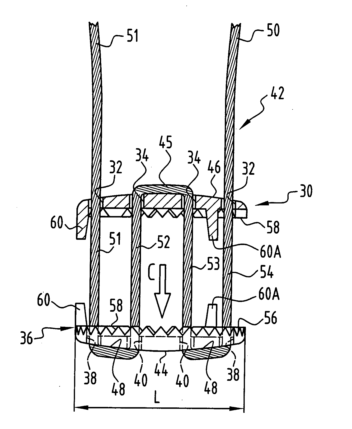
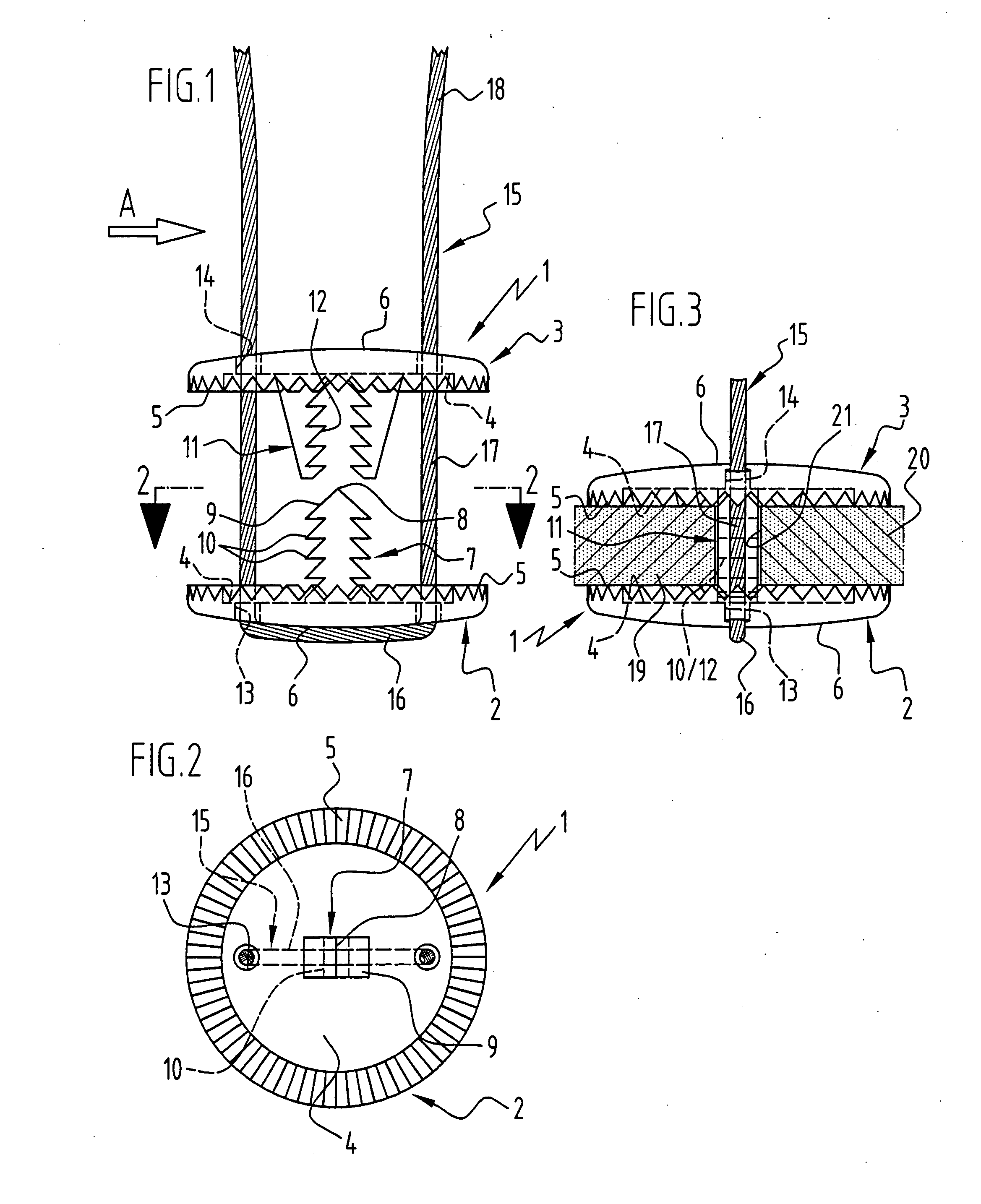
[0032] The implant 1 illustrated in FIGS. 1 to 3 incorporates two circular, plate-like bearing elements 2, 3 which comprise a serrated boundary region 5 on the flat, mutually facing inner faces 4 thereof and an external surface 6 which is slightly domed in the outward direction.

[0033] The inner bearing element 2 carries a central latching projection 7 which points towards the outer bearing element 3 and has a tip 8 with inclined glide surfa...


PUM


Abstract

An implant is provided for fixing neighbouring bone plates of the cranial bone in a simple and reliable manner. The implant comprises an outer bearing element for covering a spacing gap between the bone plates, which sits on outer surfaces of the bone plates. The outer bearing element has a first pair of outer openings and a first pair of inner openings. An inner bearing element is provided for covering the spacing gap between the bone plates, which sits on inner surfaces of the bone plates. The inner bearing element has a second pair of outer openings and a second pair of inner openings. A thread-like tensioning element is provided which is threaded through the openings of the outer and inner bearing elements in a displaceable manner, such that, when tensioned, the tensioning element draws the inner bearing element and the outer bearing element together.

Description

[0001] This application is a continuation-in-part of commonly assigned, copending U.S. patent application Ser. No. 10 / 718,851 filed on Nov. 20, 2003, which is a continuation of international patent application PCT / EP02 / 05653 filed on May 23, 2002 and claims the benefit of German patent application no. 101 28 917.0 filed on Jun. 15, 2001, each of which is incorporated herein by reference in their entirety and for all purposes.BACKGROUND OF THE INVENTION [0002] The invention relates to an implant for fixing neighbouring bone plates of the cranial bone, wherein the plates have an inner surface and an outer surface. The implant comprises an inner bearing element which covers a spacing gap between the bone plates, an outer bearing element which covers the spacing gap, and a connecting device which extends through the spacing gap and which, when the bearing elements approach one another, connects the bearing elements together by means of a latching or a clamping connection in such a manne...

Claims


Application Information

Patent Timeline
IPC IPC(8): A61B17/68
CPCA61B17/688
Inventor NESPER, MARKUSSTEINHILPER, KLAUS-DIETERWEISSHAUPT, DIETER
Owner AESCULAP AG
Why Eureka
Try Eureka