

Stent delivery catheter positioning device
- Summary
- Abstract
- Description
- Claims
- Application Information
AI Technical Summary
Benefits of technology
Problems solved by technology
Method used
Image

Examples
Embodiment Construction
[0024] The following detailed description should be read with reference to the drawings, in which like elements in different drawings are numbered identically. The drawings, which are not necessarily to scale, depict selected embodiments and are not intended to limit the scope of the invention. Examples of constructions, materials, dimensions and manufacturing processes are provided for selected elements. Those skilled in the art will recognize that many of the examples provided have suitable alternatives that may be utilized.
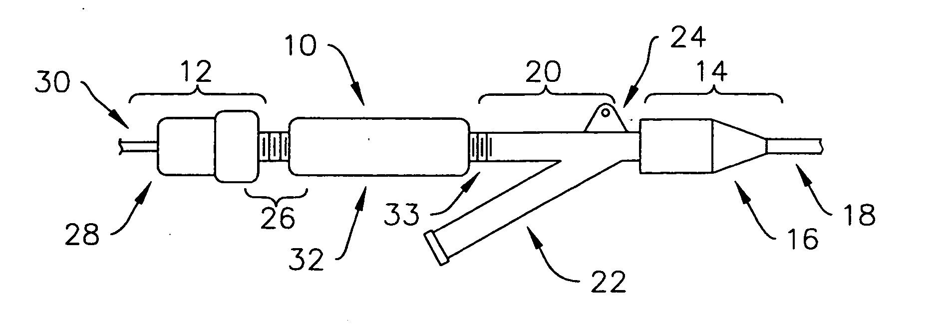
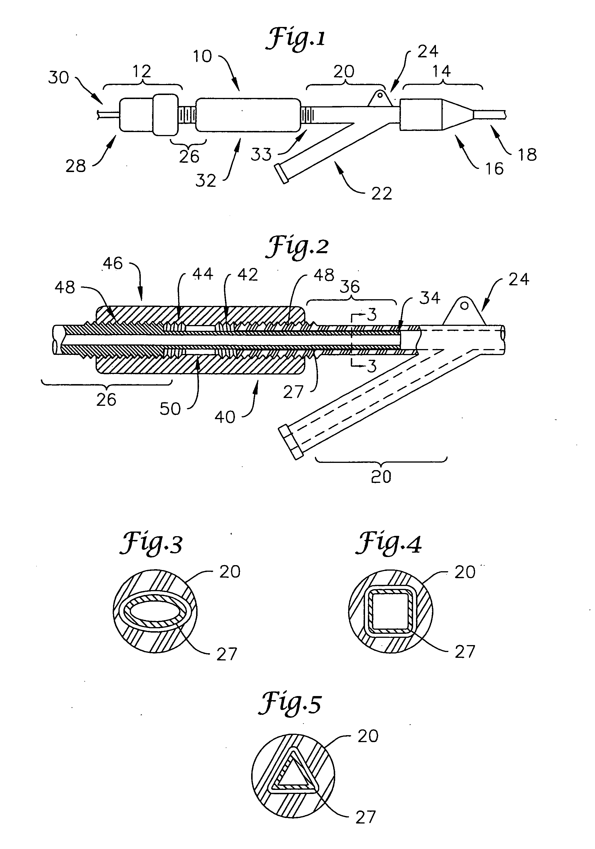
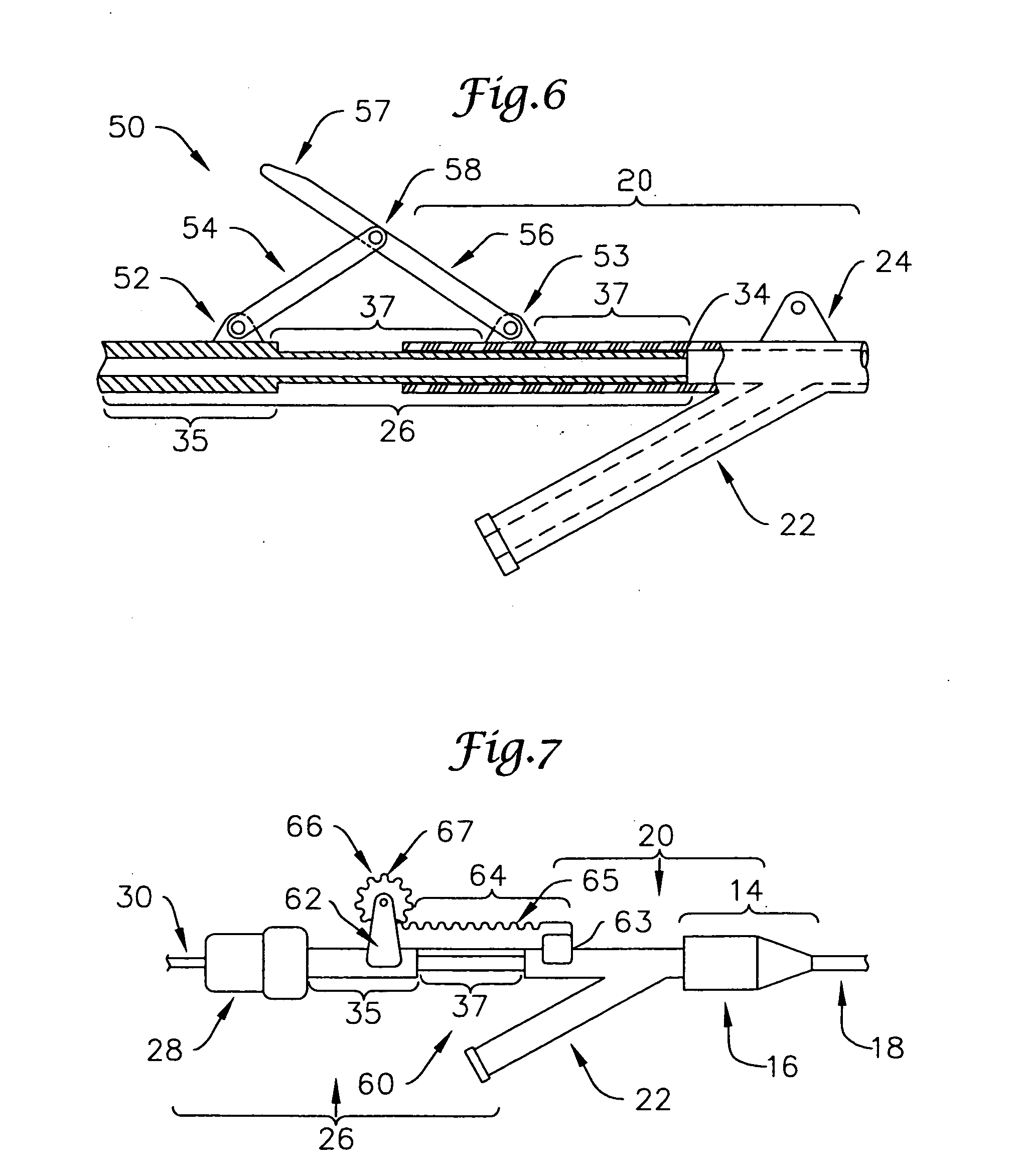
[0025] Referring now to the drawings, FIG. 1 shows one embodiment of a hub assembly unit 10 of the present invention. Hub assembly unit 10 comprises a proximal end 12 and a distal end 14. Distal end 14 includes a linking mechanism 16 connecting hub assembly unit 10 to a first medical device 18. In preferred embodiments, first medical device 18 is a catheter, and more specifically, a guide catheter. A proximal fitting is positioned at the proximal end of guide ...
PUM
 Abstract
Description
Claims
Application Information