
Spinal implant

a technology of spine implants and implants, applied in the field of spine implants, can solve the problems of most cancellous allografts not being used, and achieve the effect of improving the quality of life and reducing the risk of surgery

Inactive Publication Date: 2005-03-03
LEE CASEY K
View PDF22 Cites 8 Cited by
  • Summary
  • Abstract
  • Description
  • Claims
  • Application Information

AI Technical Summary

Benefits of technology

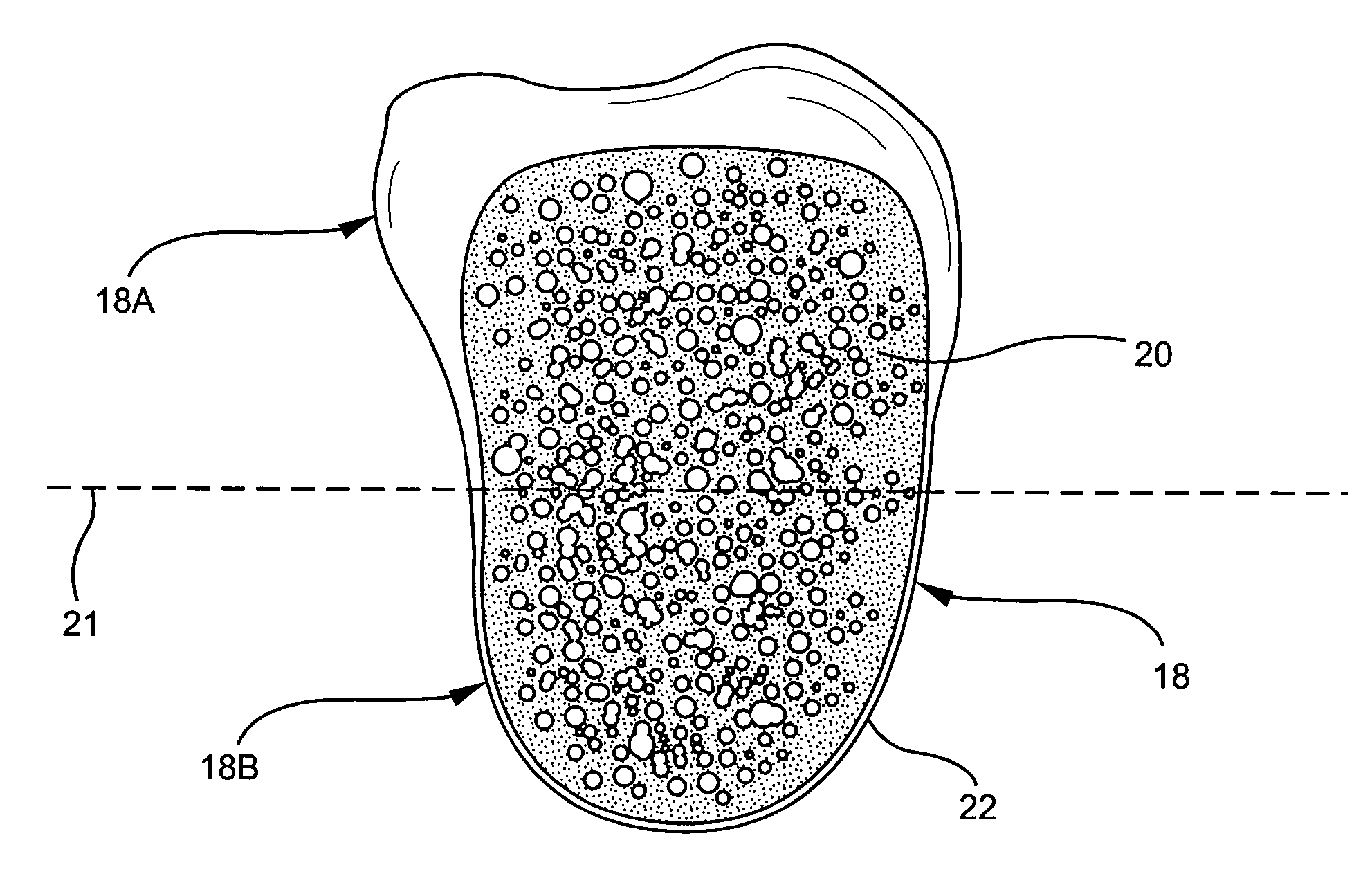
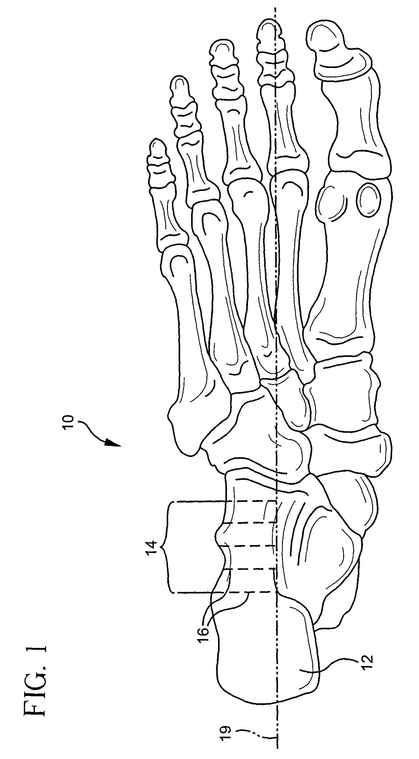
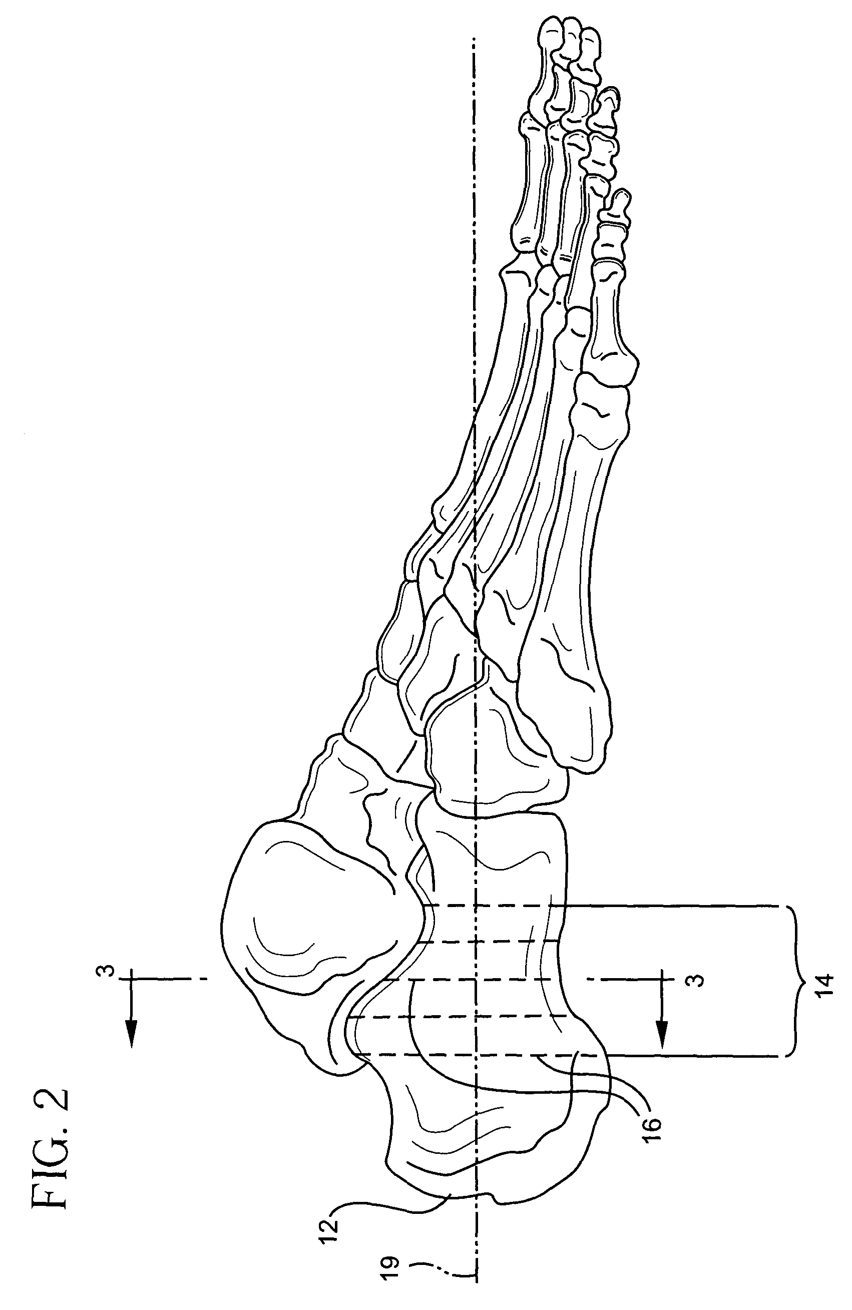
[0007] In accordance with one or more embodiments of the present invention, a thoracic and lumbar spinal implant are provided. As used herein, the term “thoracic spine” includes the thoracic spine region (T1-T12) and the thoracolumbar spine region (T11-L1), and the term “lumbar spine” includes the lumbar and lumbosacral spine (L1-S1). The implant preferably comprises a solid body of greater than 10% dense cancellous bone that is sized and shaped for placement between to lumbar vertebral bodies. In certain preferred embodiments, the graft comprises substantially dense cancellous bone that is sized and shaped for placement between two lumbar vertebral bodies. In preferred embodiments, the implant is an allograft. The implant is capable of bearing weight in the thoracic spine and lumbar spine of a human being. One or more embodiments relate to a thoracic or lumbar spinal implant allograft comprised of calcaneus. Another embodiment of the invention relates to a method of performing a spinal fusion on a patient comprising placing an implant comprised of greater than 10% dense cancellous bone between two thoracic or lumbar vertebral bodies. In preferred embodiments, the implant comprises an allograft of calcaneus. In still another embodiment of the invention, a method of preparing a spinal implant comprises cutting a portion of a calcaneus from a donor.

Problems solved by technology

It is believed, however, that mostly cancellous allografts have not been used in the lumbar or thoracic spine or thoracic spine area because cancellous bone does not have the weight bearing properties required for implants subjected to mechanical loads in these regions of the spine.
Although a variety of allograft implants exist for the region below the cervical spine, and in particular, the lumbar spine, improved allograft implants are needed, particularly as the supply of allografts is currently limited.

Method used


Image

  • Spinal implant
  • Spinal implant
  • Spinal implant

Examples


Embodiment Construction

[0014] Before describing several exemplary embodiments of the invention, it is to be understood that the invention is not limited to the details of construction or process steps set forth in the following description. The invention is capable of other embodiments and of being practiced or carried out in various ways.

[0015] In overview, one or more embodiments of the invention relates to a thoracic or lumbar spinal implant. According to certain preferred embodiments an implant comprised of greater than about 10% by volume cancellous bone is capable of supporting the weight in the lumbar spine of a patient when implanted between two vertebrae. Preferably, the cancellous bone is dense cancellous bone. In preferred embodiments, the implant is comprised of substantially cancellous bone. As used herein for one or more embodiments, the phrase “substantially cancellous bone” means bone that is comprised of greater than about 50% cancellous bone by volume. In preferred embodiments, calcaneu...


PUM


Abstract

Lumbar and thoracic spinal implants comprised of substantially cancellous bone and / or calcaneus are disclosed. The graft lumbar and thoracic spinal implants have sufficient load bearing capacity to withstand the loads of the lumbar and thoracic spine.

Description

FIELD OF THE INVENTION [0001] The invention relates to spinal implants and methods for their preparation and use. BACKGROUND OF THE INVENTION [0002] Intervertebral fusion is one of many procedures used in the treatment of degenerative and traumatic spinal disorders such as disc disease. Interbody fusion stabilizes the spine and contributes to reducing the pain associated with degenerative disc disease. Fusion procedures are most frequently performed in the lumbar spine, however, they are also performed in the cervical spine and thoracic spine. Generally, there are several types of lumbar spinal fusion procedures: posterior lumbar interbody fusion (PLIF); anterior lumbar interbody fusion (ALIF); transforaminal interbody lumbar fusion (TLIF); posterior fusion; and postero-lateral fusion. [0003] In posterior lumbar interbody fusion, (PLIF), two adjacent vertebral bodies are fused together by removing the affected disc and inserting an implant between the vertebral bodies, maintaining t...

Claims


Application Information

Patent Timeline
Patent Type & Authority Applications(United States)
IPC IPC(8): A61F2/28A61F2/44
CPCA61F2/28A61F2/4455A61F2310/00359A61F2002/30057A61F2002/2817
Inventor LEE, CASEY K.
Owner LEE CASEY K
Learn More