
Selectively resampling particle filter

Inactive Publication Date: 2005-03-03
LOCKHEED MARTIN CORP
View PDF5 Cites 13 Cited by
  • Summary
  • Abstract
  • Description
  • Claims
  • Application Information

AI Technical Summary

Benefits of technology

The present invention, in at least one embodiment, provides an implementation of weight and particle position adjustment (i.e., resampling) that is performed to keep the weights reasonably even without introducing excessive resampling noise. The resampling method described herein, at least in one embodiment, is computer efficient.

Problems solved by technology

In many such cases, complete information about the signal is not readily available.
However, the Kalman filter has very stringent requirements on the possible signal dynamics and on the form of the sensor function.
As well, it provides no direct method to provide predictors or smoothers.
However, the problems that can be solved in this manner still form a small subset of the whole space of real world problems.
The approximations given hitherto are based upon updated particle locations and are usually of poor quality.
These actions themselves entail an unavoidable loss of asymptotic optimality in increasing numbers of particles for the filter.
If only some particles are considered for redistribution, there are still some degenerative effects working against optimality, and the calculation of the average weight for a subset of the particles is cumbersome.
However, a great amount of computation is involved in redistributing all of the particle states at each time step.
This effort is especially pronounced if the particle data must travel between processing units in a distributed architecture.
Further, redistributing all of the particles is undesirable as it induces undue extra randomness that impairs path space capabilities and downgrades performance as will be explained below.

Method used


Image

  • Selectively resampling particle filter
  • Selectively resampling particle filter
  • Selectively resampling particle filter

Examples


Embodiment Construction

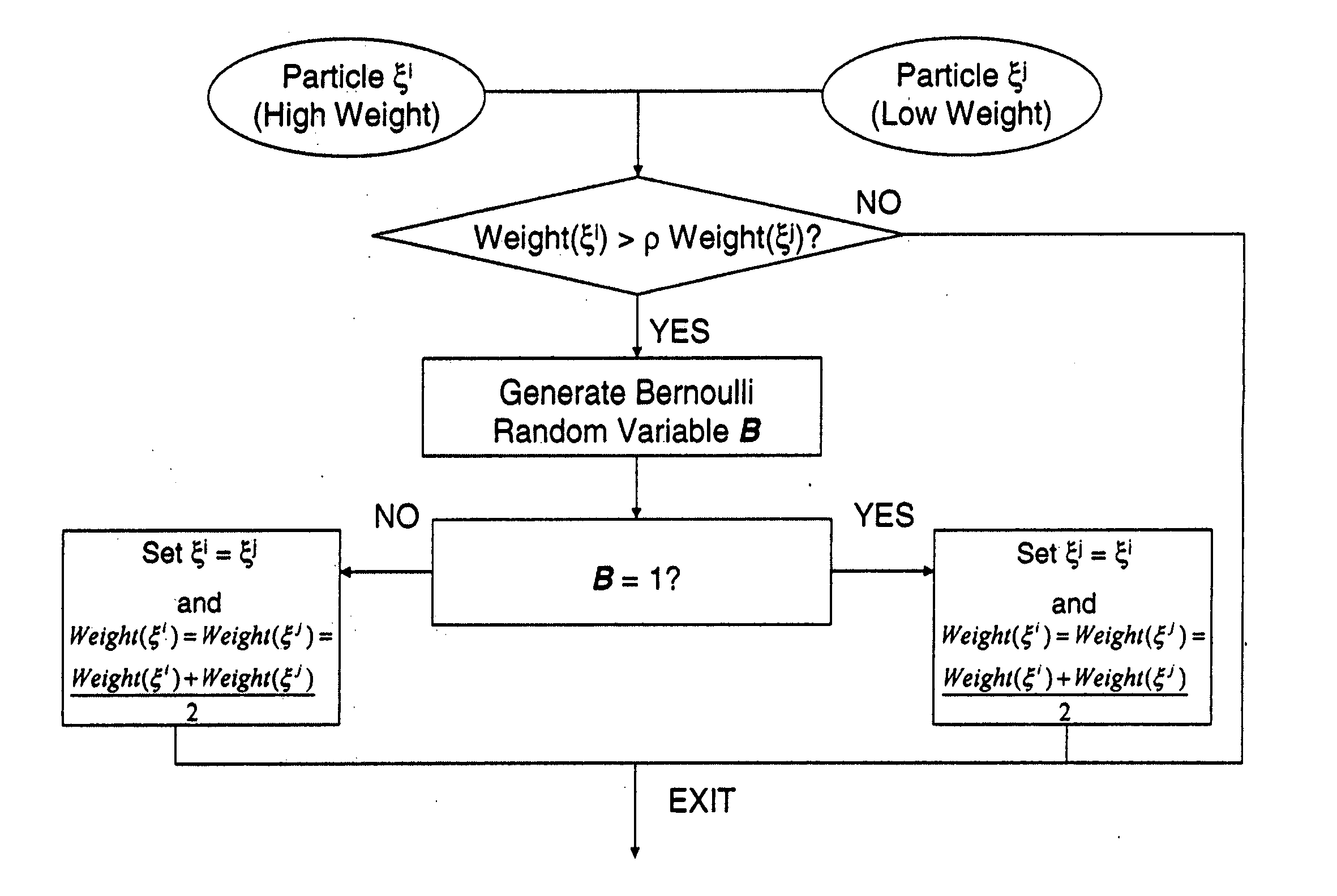
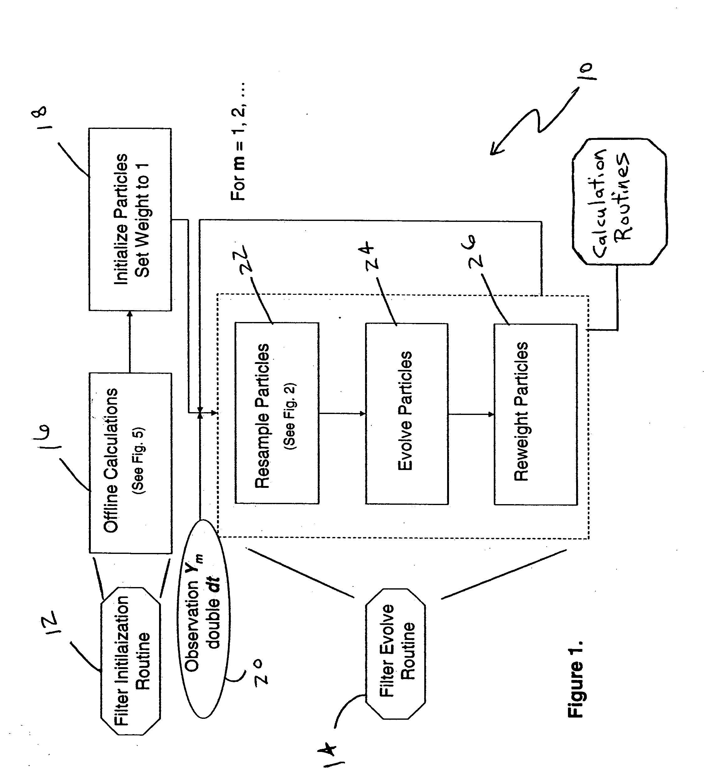
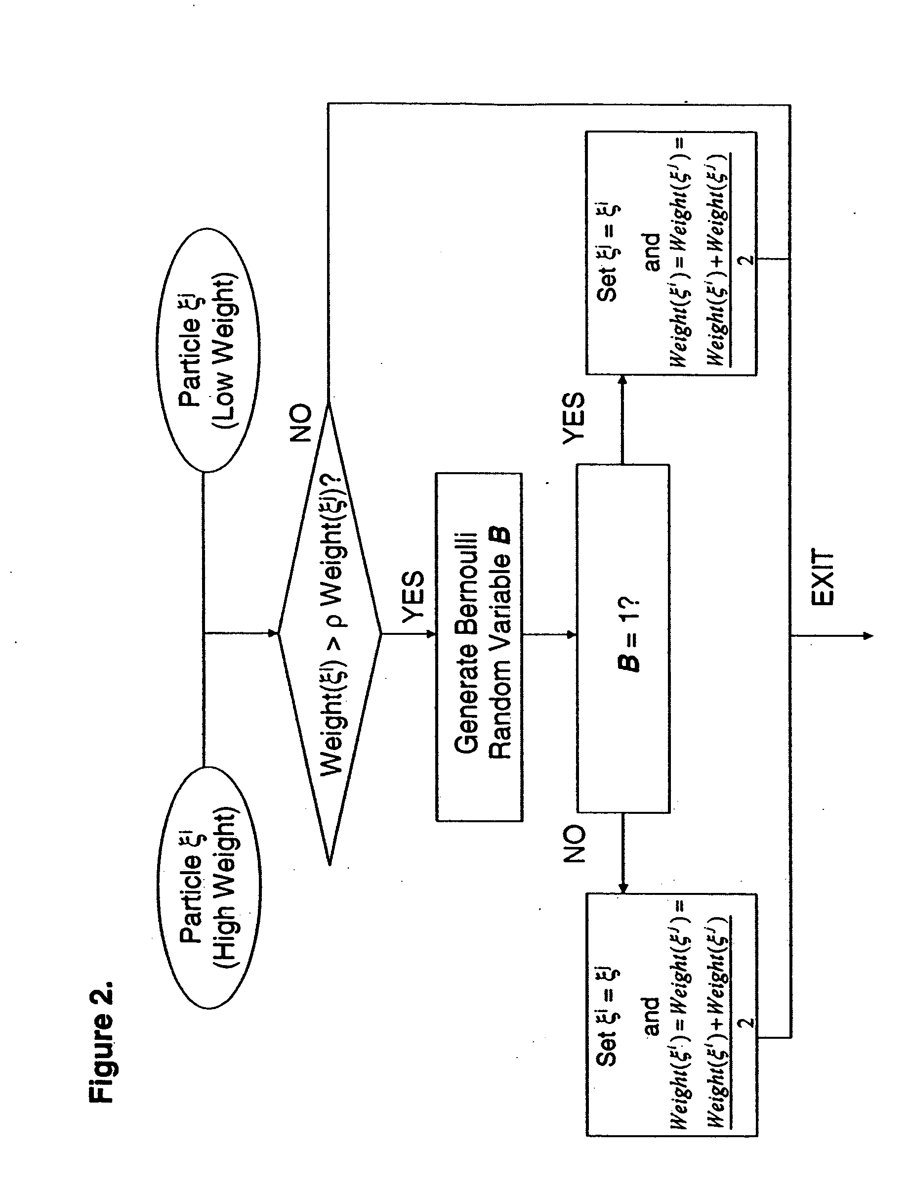
One or more embodiments of the present invention shall be described with reference to the generalized exemplary SERP filtering procedure 10 shown in FIG. 1. In addition, various embodiments of the procedure shall be described with reference to the FIGS. 2-9.

In general, at least in one embodiment, a particle filter is employed so that particle locations provide signal information to construct an approximated conditional distribution of probabilistic signal state. For an optimal tracking filter, current particles are used with resampled weight values. To construct an optimal predicting filter, copies of the current particles are evolved forward to the time for which the prediction is to occur. A pairwise-interacting selectively resampling particle filter according to the present invention allows the construction of optimal path space smoothing and tracking filters. Ancestor particles retain probabilistic data about the likely historical path of the signal. Then these particles, wei...


PUM


Abstract

A method, and program for implementing such method, for use in estimating a conditional probability distribution for past signal states, current signal states, future signal states, and / or complete pathspace of a non-linear random dynamic signal process, includes providing sensor measurement data associated with the non-linear random dynamic signal process. State data including at least location and weight information associated with each of a plurality of particles is provided as a function of the sensor measurement data that collectively probabilistically represents the state of the non-linear random dynamic signal process at time t. An estimate of the conditional probability distribution is computed for the signal state based on the state data for particles under consideration. The particles under consideration are resampled upon receipt of sensor measurement data. The resampling includes comparing weight information associated with a first particle with weight information associated with a second particle to determine if the state data of the first and second particles is to be adjusted. The first particle is the highest weighted particle under consideration and the second particle is the lowest weighted particle under consideration.

Description

BACKGROUND OF THE INVENTION The present invention relates to efficient nonlinear asymptotically optimal tracking, smoothing, and prediction of dynamic processes in real time. Many industries require a system to determine the location and state of a signal in some domain based upon corrupted, distorted, incomplete observations of this signal. For example, one might want to know the position, orientation, and velocity of an aircraft, collectively defining the signal, over a busy airport. Additionally, it might be important to know where the aircraft is likely to be in the future and what path it has taken in the past. In many such cases, complete information about the signal is not readily available. Instead, only distorted, corrupted, partial information given by discrete-time observations is provided. In the aircraft example, the only data provided to the airport might be noisy transmissions of truncated altimeter readings and range data for the aircraft that arrive at two second...

Claims


Application Information

Patent Timeline
IPC IPC(8): G05B13/02G06F17/18
CPCG05B13/021
Inventor KOURITZIN, MICHAEL A.
Owner LOCKHEED MARTIN CORP
Learn More