Method of making a two-layer lap winding for a multiphase electrical machine

a multi-phase electrical machine and lap winding technology, applied in the direction of magnetic bodies, magnetic circuit shapes/forms/constructions, instruments, etc., can solve the problems of reducing the cooling air that reaches these places, reducing the current load capacity of the lap winding, and especially disadvantageous coil connectors outside the winding ends, etc., to achieve the effect of impaired cooling and more nois

Active Publication Date: 2007-12-04
SEG AUTOMOTIVE GERMANY GMBH
View PDF7 Cites 8 Cited by
  • Summary
  • Abstract
  • Description
  • Claims
  • Application Information

AI Technical Summary

Benefits of technology

[0008]The method according to the invention for making a two-layer lap winding with the features described above has the advantage that at least one part of the coil connectors are arranged within the winding ends formed by the individual coil units of the respective phases. Thus the corresponding two-layer lap winding and especially the winding ends with the coil connectors are cooled better. The current load capacity of the lap winding is thus improved, the current production of the electrical machine equipped with these coil connectors is improved in regard to the current load capacity and efficiency.
[0011]When the at least one further first coil unit of at least one further phase is wound over two already laid coil connectors, it is possible to obtain a three-phase lap winding, whose coil connectors are assembled entirely within the winding ends. From the outside the winding ends of the three-phase lap winding appear uniform without discontinuities, which can lead to more noise and impaired cooling.

Problems solved by technology

This arrangement of the coil connectors outside the winding ends is especially disadvantageous, when, as is usually the case for a generator, cooling air flowing around the winding ends cools them.
These sorts of exterior coil connectors produce an unsymmetrical arrangement on the surface of the winding ends, so that noise producing flow interruptions or eddies result and consequently the side of the winding on which the coil connections are arranged is critical.
Furthermore it is disadvantages that these types of coil connectors cover a part of the wires of the winding ends and consequently can only reduce the cooling air that reaches these places.
As a result the cooling action at these locations is impaired so that the temperature increases, the current load capacity of the lap winding drops and the entire efficiency of the machine is reduced below what it could be.

Method used


Image

  • Method of making a two-layer lap winding for a multiphase electrical machine
  • Method of making a two-layer lap winding for a multiphase electrical machine
  • Method of making a two-layer lap winding for a multiphase electrical machine

Examples


Embodiment Construction

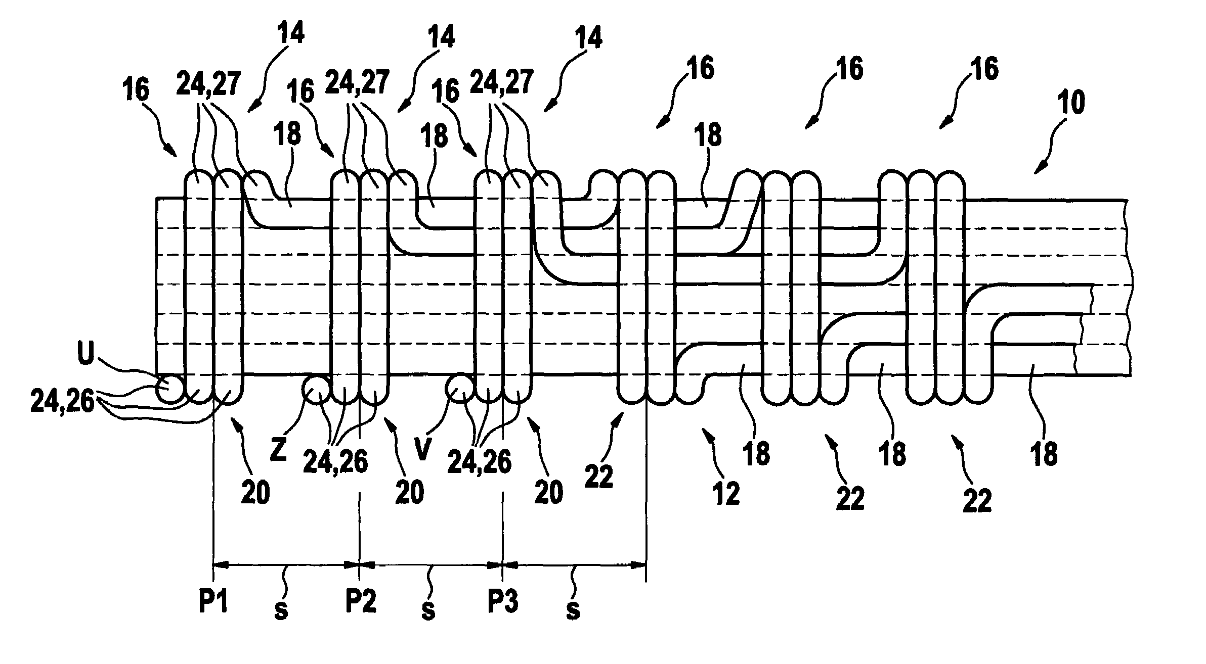
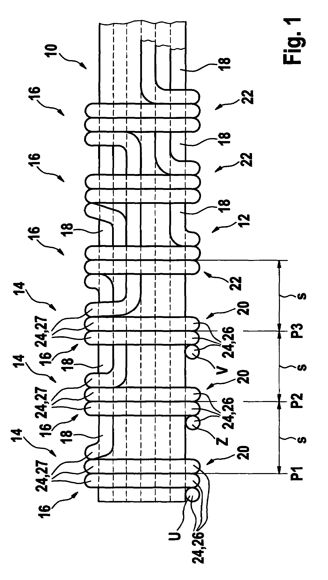
[0029]A so-called winding bar 10, which acts as an aid, for making a multiphase two-layer lap winding for an electrical machine, is shown in detail in FIG. 1. The lap winding 12 comprises three-phase windings 14 in the embodiment shown in FIG. 1. These three-phase windings 14 each have a winding beginning U, Z or V. The individual phase windings 14 comprise coil units 16 and coil connectors 18. Each phase winding 14 has a so-called first coil unit 20 and second coil unit 22. The first coil units 20 and the second coil units 22 are wired alternately with each other and connected with each other by coil connectors 18. As a result a first coil unit 20 in one phase winding is connected with a coil connector 18 to a second coil unit 22, which again is connected by another coil connector 18 with another first coil unit 20.

[0030]FIG. 1 shows the lap winding 12, which is made as follows:

[0031]First a first coil unit 20 with a predetermined number of loops is wound around the winding bar 10 ...


PUM

PropertyMeasurementUnit
temperatureaaaaaaaaaa
current load capacityaaaaaaaaaa
current carrying behavioraaaaaaaaaa

Abstract

The method of making a two-layer lap winding (12) for a multiphase electrical machine includes the steps of winding a first coil unit (20) of a first phase winding (14) around a winding bar (10); subsequently laying a coil connector (18) of the first phase winding (14) in a first direction and then winding at least one other coil unit (16) of at least one other phase winding (14) around the winding bar (10) and over the coil connector (18). Subsequently a second coil unit (22) of the first phase winding (14) is wound around the winding bar (10) following all first coil units of all phase windings and after all coil connectors from the first coil units are laid. A method of making a stator from the two-layer lap winding (12) is also described.

Description

CROSS REFERENCE TO RELATED DOCUMENT[0001]This application claims priority of invention based on German Patent Application No. 103 29 576.3, filed on Jun. 30, 2003, under 35 U.S.C. 119.BACKGROUND OF THE INVENTION[0002]U.S. Pat. No. 5,197,180 discloses a method of making a two-layer lap winding using a so-called winding bar or beam. The sequence of the individual winding steps for making this three-phase winding is such that all coil connectors of the coil units are arranged outside the winding ends. This arrangement of the coil connectors outside the winding ends is especially disadvantageous, when, as is usually the case for a generator, cooling air flowing around the winding ends cools them. These sorts of exterior coil connectors produce an unsymmetrical arrangement on the surface of the winding ends, so that noise producing flow interruptions or eddies result and consequently the side of the winding on which the coil connections are arranged is critical. Furthermore it is disadva...

Claims


Application Information

Patent Timeline
Patent Type & Authority Patents(United States)
IPC IPC(8): H02K15/00H02K3/04H02K3/28H02K15/02H02K15/04H02K15/06
CPCH02K3/28H02K15/026H02K15/0471H02K15/06Y10T29/49073Y10T29/49174Y10T29/49071Y10T29/49009Y10T29/49012
Inventor KREUZER, HELMUTRAU, EBERHARDBEZNER, REINHARD
Owner SEG AUTOMOTIVE GERMANY GMBH
Why Eureka
Try Eureka