
System and method analyzing design elements in computer aided design tools

a technology of design elements and computer aided design, applied in computer aided design, program control, instruments, etc., can solve the problems of large design complexity, inability to perform large design, and large design inherently complex,

Inactive Publication Date: 2005-03-03
HEWLETT PACKARD DEV CO LP
View PDF68 Cites 7 Cited by
  • Summary
  • Abstract
  • Description
  • Claims
  • Application Information

AI Technical Summary

Benefits of technology

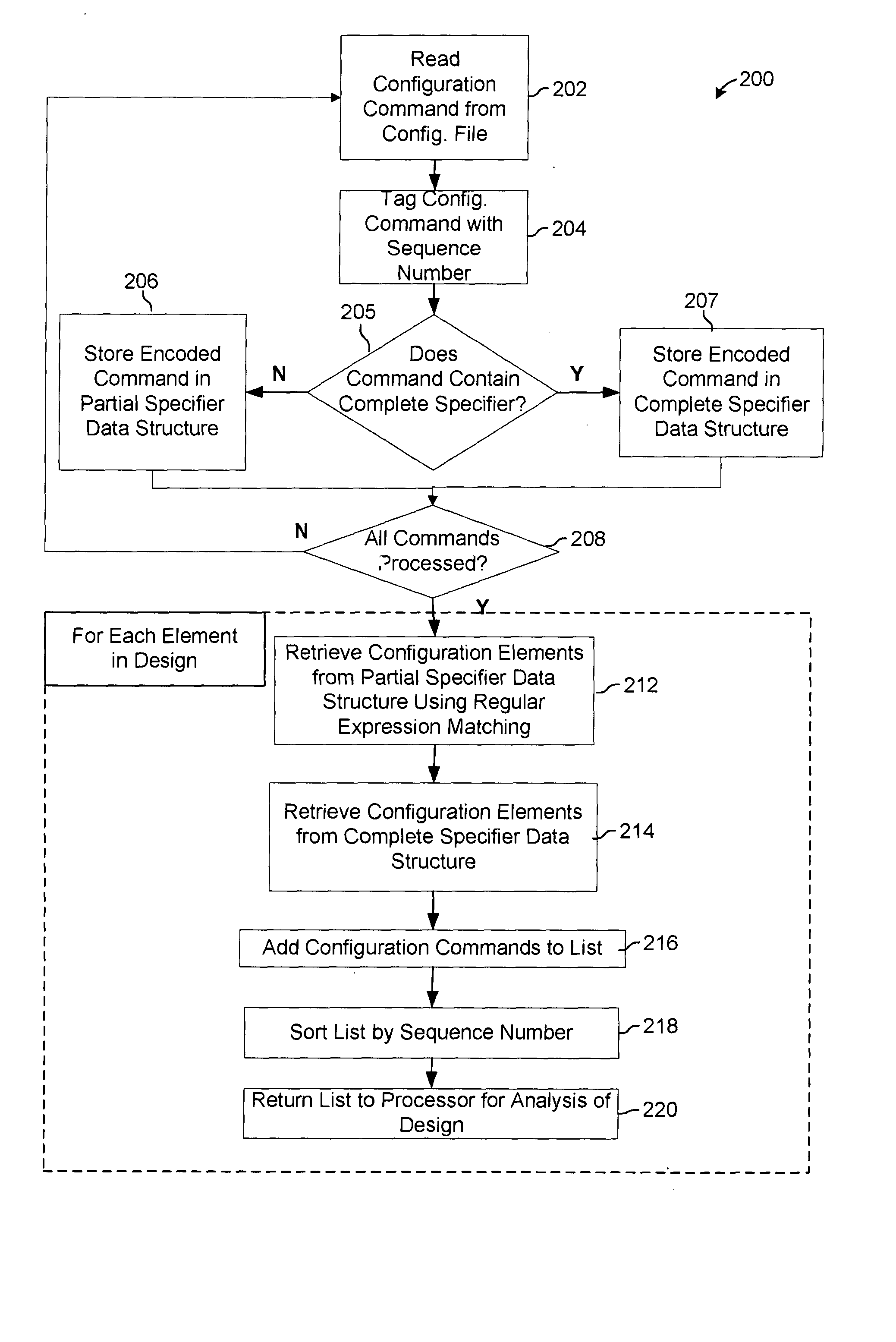
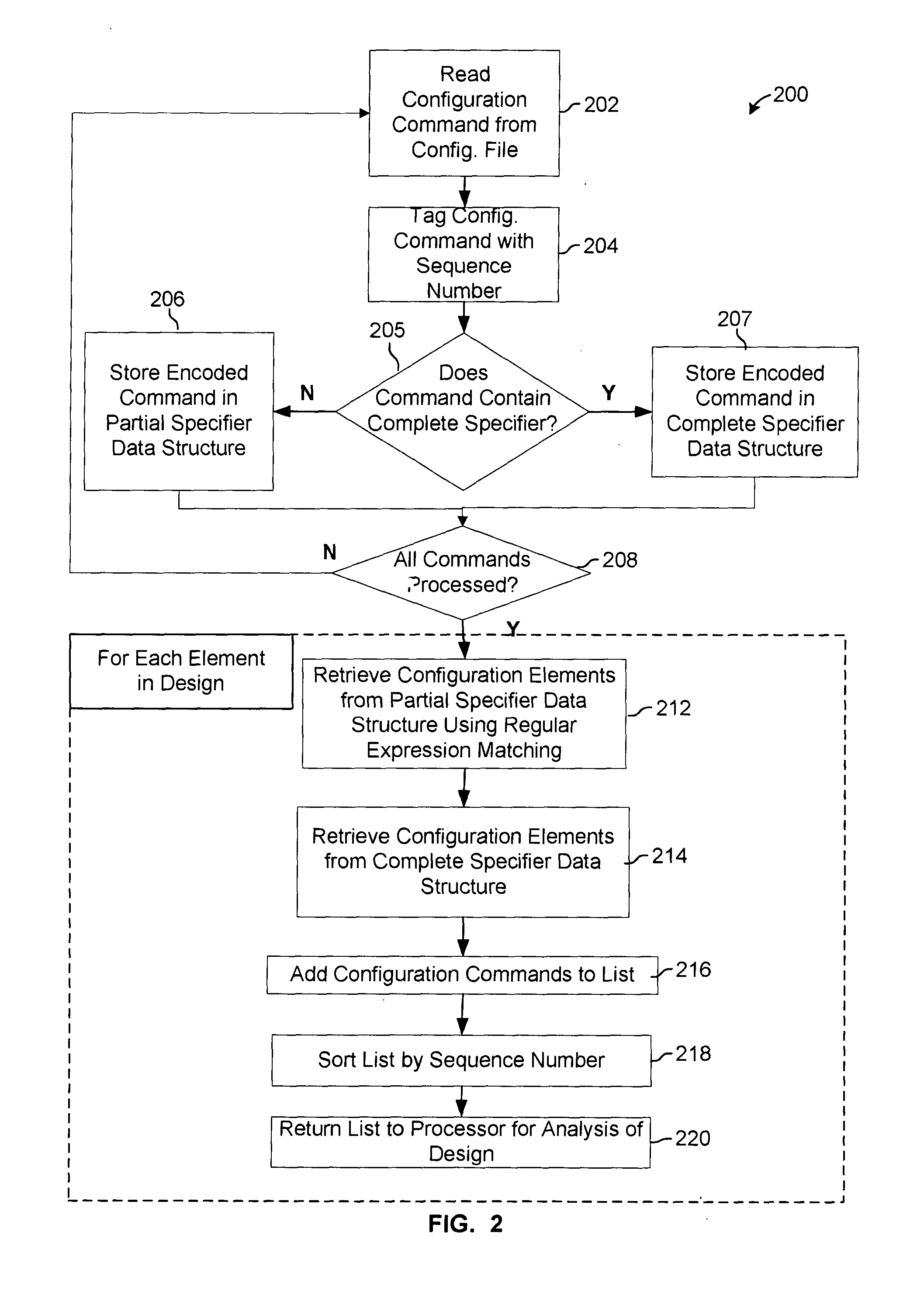
The present system is a method for analyzing design elements in a CAD tool design. It involves generating a configuration element for each configuration command in a configuration file, and organizing them in order of appearance in the file. This configuration element is then applied to the design element of interest in the order indicated by the sequence number. The technical effect of this system is that it allows for efficient analysis of design elements by automatically organizing them in the correct order and applying them to the design element of interest.

Problems solved by technology

These combined design and analysis calculations consume a large portion of processor power and memory space of a computer system when operating the CAD tool.
A large design is inherently complex; thus, the calculations performed by the CAD tool are numerous and lengthy.
To further complicate microprocessor design, the number of design elements typically increases as processor technology advances.
Presently, CAD tool calculations performed by an analysis module on a design are numerous and may last many hours or even days.
When calculations are performed on designs having a billion design elements or more, a determination of whether the new portion is acceptable may not be made until the next day or beyond, since the CAD tool may need to perform complex calculations on large designs that include large amounts of data.
Furthermore, physical limits of computer memory may make performing the complex calculations an impossibility.
Since the analysis is a time consuming process, productivity may be lost, as engineers must wait for analysis results.
Continuous lost productivity due to lengthy development times slows technology advancement and can result in significant costs, as well as lost business.

Method used


Image

  • System and method analyzing design elements in computer aided design tools
  • System and method analyzing design elements in computer aided design tools
  • System and method analyzing design elements in computer aided design tools

Examples


Embodiment Construction

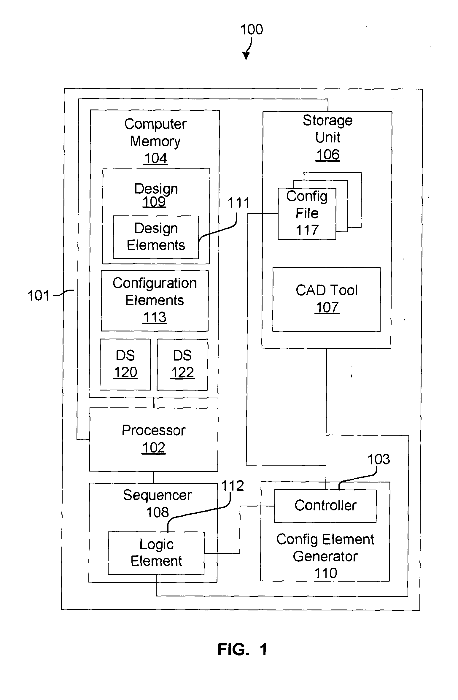
FIG. 1 shows CAD system 100 configured for generating configuration elements 113, in accord with one embodiment of the present system. A configuration element is an encoding of data comprising formatted information associated with a design. More specifically, a configuration element is an encoding of information contained in a configuration command (described below). Multiple configuration elements may pertain to a single design element, and a single configuration element may pertain to multiple design elements. For example, in some instances multiple configuration elements can be used to describe individual characteristics of a design element, while in other instances one configuration element can be used to describe all of the characteristics of one particular design element. A design element (i.e., of design elements 111) is a single component, a net, or a group of elements of design 109 that structurally define the design generated by CAD tool 107. For example, an electronic des...


PUM


Abstract

System and method for analyzing design elements in a CAD tool design. A configuration element generator encodes information in a configuration command to generate a configuration element associated with at least one of the design elements. A sequencer, coupled to the configuration element generator, tags the configuration element with a sequence number. A computer memory, coupled to the sequencer, stores the configuration element. A processor, coupled to the computer memory, applies, to the design element that is of interest, each stored said configuration element associated with the design element of interest, in an order indicated by the sequence number. A configuration element is an encoding of data comprising formatted information associated with a design.

Description

BACKGROUND Computer aided design (CAD) tools and computer aided engineering (CAE) tools are used to create and analyze various types of designs. Hereinafter, a CAD tool and a CAE tool are both referred to simply as a CAD tool. The designs are used to support a variety of fields, such as architecture, civil engineering, mechanical engineering, and electrical engineering. An M-CAD tool and an E-CAD tool are two types of CAD tools. An M-CAD tool creates and analyzes mechanical engineering designs and an E-CAD tool creates and analyzes electrical / electronic engineering designs, such as schematics of an electronic circuit. A CAD tool performs numerous calculations. These calculations can include design calculations as well as analysis calculations. The analysis calculations are used to determine characteristics of engineering components used in the designs. Hereinafter, engineering components in a design are referred to as design elements. For example, the E-CAD tool can determine resi...

Claims


Application Information

Patent Timeline
Patent Type & Authority Applications(United States)
IPC IPC(8): G06F17/50
CPCG06F2217/78G06F17/50G06F2119/06G06F30/00
Inventor KELLER, S. BRANDONROGERS, GREGORY DENNISROBBERT, GEORGE HAROLD
Owner HEWLETT PACKARD DEV CO LP
Learn More