Apparatus for preventing motor overload of vacuum cleaner

a technology for vacuum cleaners and apparatuses, applied in the field of vacuum cleaners, can solve the problems of requiring an overly complex structure, and affecting the operation of vacuum cleaners, etc., and achieves the effects of reducing manufacturing costs, satisfying sealing, and reducing the number of components

Inactive Publication Date: 2005-03-10
SAMSUNG GWANGJU ELECTRONICS CO LTD
View PDF2 Cites 5 Cited by
  • Summary
  • Abstract
  • Description
  • Claims
  • Application Information

AI Technical Summary

Benefits of technology

[0028] Instead of forming the opening / closing portion with additional material, such as rubber, satisfactory sealing can be ensured by tapering the opening / closing portion and the aperture even when surface contact occurs between the opening / closing portion and the aperture. Additionally, the number of components can be reduced, and with the omission of expensive flexible material, such as rubber, the manufacturing cost can be reduced.

Problems solved by technology

However, when the filtering chamber 7 is filled with dust, or if the suction pipe 3 becomes clogged, fluid communication through the system is hampered, and therefore, the driving motor 1 suffers an overload condition as a result of lack of available air in the suction process.
However, the motor overload preventing apparatus 20 requires an overly complex structure.
Further, because the opening / closing member 25 is usually made of expensive material, such as rubber, in order to ensure sufficient sealing of the opening / closing member 25, manufacturing cost increases.

Method used


Image

  • Apparatus for preventing motor overload of vacuum cleaner
  • Apparatus for preventing motor overload of vacuum cleaner
  • Apparatus for preventing motor overload of vacuum cleaner

Examples


Embodiment Construction

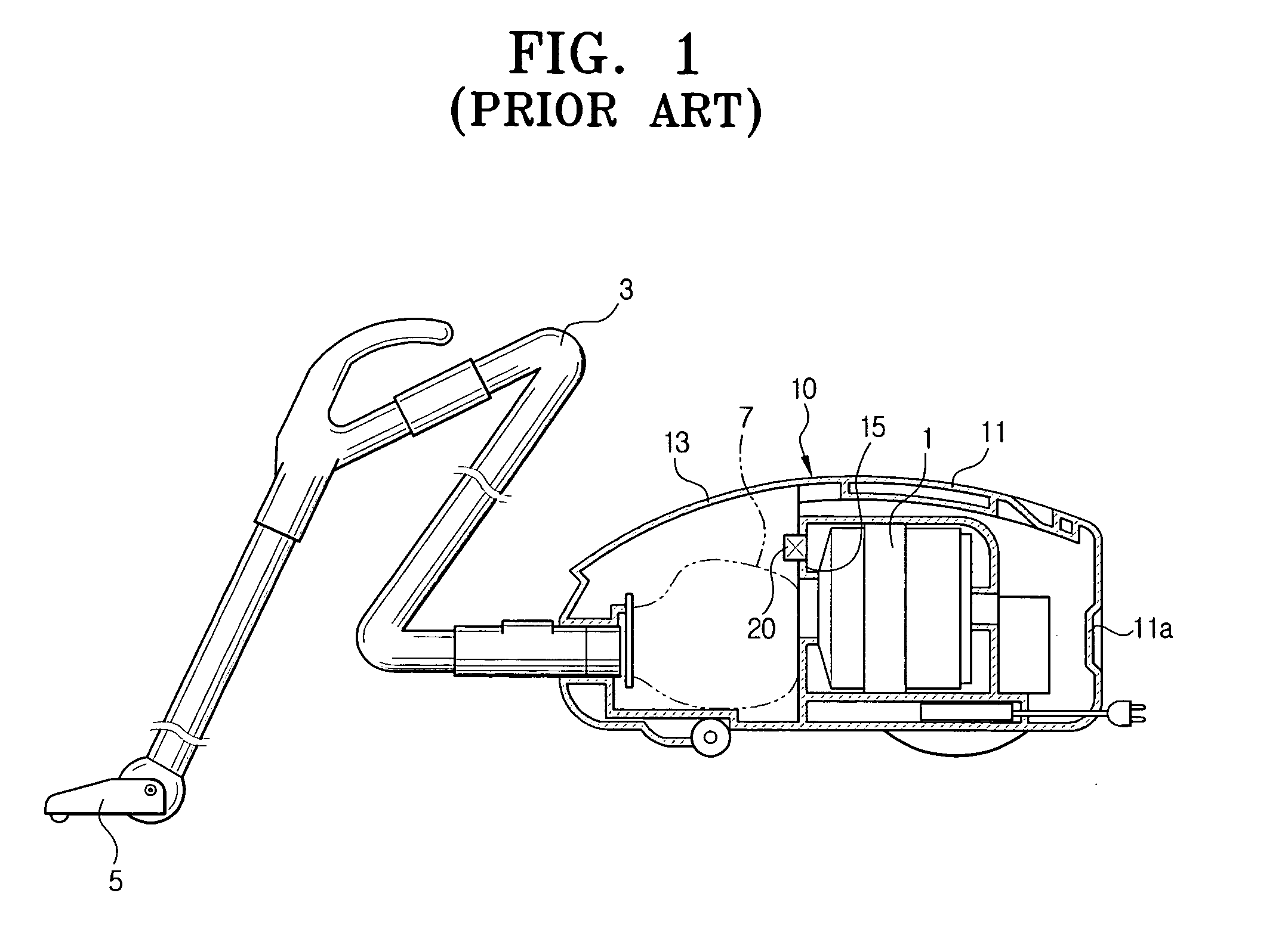
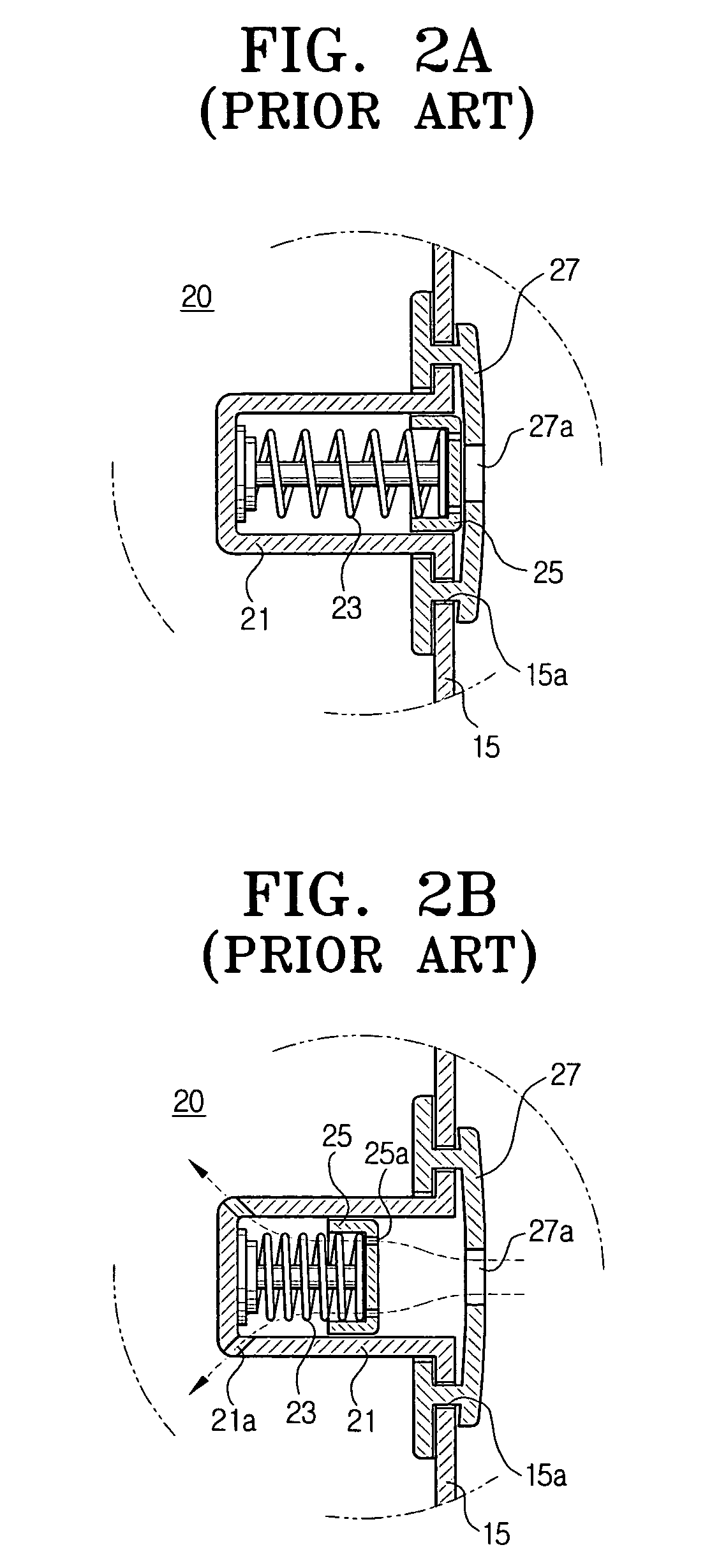
[0036] Hereinafter, the present invention will be described in detail with reference to the accompanying drawings. Throughout the description, the elements similar to, or identical with, those described in the background art as illustrated in FIGS. 1 and 2A-B will be identified by the same reference numerals and further detailed description of the structure and function thereof will rely on the description made above.

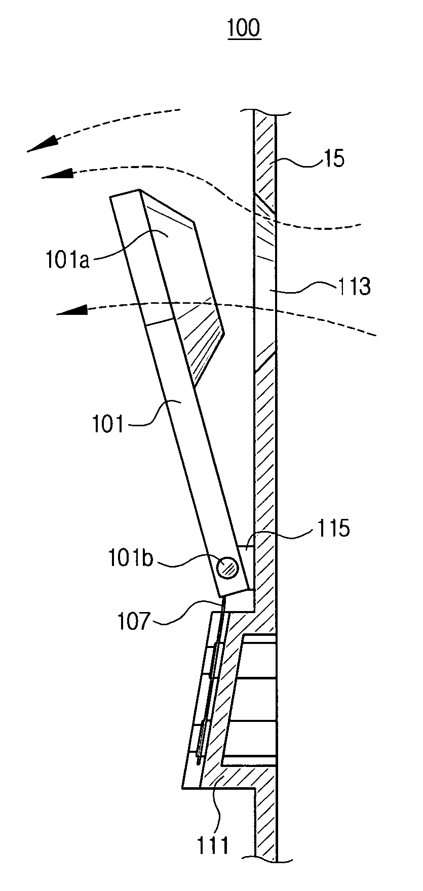
[0037] FIGS. 3A-C and 4A-B are views of a motor overload preventing apparatus for use in a vacuum cleaner according to a first preferred embodiment of the present invention.

[0038] Referring now to FIGS. 3 and 4, the first preferred embodiment of the motor overload preventing apparatus 100 includes a damper body 101 and a resilient member 107.

[0039] A tapered opening / closing portion 101a is formed in an end of the damper body 101, while the other end of the damper body 101 is connected to the partition 15 of the vacuum cleaner by a hinge, as shown. More specifically, ...


PUM


Abstract

A motor overload preventing apparatus for a vacuum cleaner includes a damper body and an resilient member. The damper body has an opening/closing portion formed on one end, to selectively block a tapered aperture of a body frame of the vacuum cleaner, and the opening/closing portion is tapered to correspond in shape with the aperture. The resilient member resiliently biases the opening/closing portion toward a direction of closing the aperture. The damper body is movably disposed to rotate so as to selectively open and close the aperture, and to this end, it is preferred that the damper body is connected by a hinge to the body frame. Satisfactory sealing can be ensured even when there is surface contact between the opening/closing portion and the aperture without requiring additional material, such as a rubber. Additionally, the number of components can be reduced, and with the omission of flexible material, such as rubber, the manufacturing costs can be reduced.

Description

BACKGROUND OF THE INVENTION [0001] 1. Field of the Invention [0002] The present invention relates generally to a vacuum cleaner, and more particularly, to an apparatus for preventing overload of a driving motor when it generates a suction force for a vacuum cleaner. [0003] 2. Description of the Related Art [0004] Generally, a vacuum cleaner draws in air and entrained dust by using a suction force that is generated by a driving motor. FIG. 1 schematically shows such a conventional vacuum cleaner. [0005] Referring to FIG. 1, a conventional vacuum cleaner includes a body 10 in which a driving motor 1 is mounted, a suction pipe 3 which is in fluid communication with the body 10 at one of its ends and a suction nozzle 5 which is formed at the other end of the suction pipe 3 from the end connected to body 10. The body 10 includes a motor housing portion 11, in which the driving motor 1 is disposed, and a dust collecting housing portion 13, that includes a filtering portion 7 for filtering...

Claims


Application Information

Patent Timeline
Patent Type & Authority Applications(United States)
IPC IPC(8): A47L9/00A47L9/10A47L9/19A47L9/28
CPCA47L9/0072A47L9/2889A47L9/2821A47L9/19A47L9/00
Inventor JEON, KYONG-HUI
Owner SAMSUNG GWANGJU ELECTRONICS CO LTD
Why Eureka
Try Eureka