Piston and a power cylinder fitted therewith

a technology of power cylinder and piston, which is applied in the direction of mechanical equipment, engines without rotary main shafts, braking systems, etc., to achieve the effect of effective damping

Inactive Publication Date: 2008-01-29
FESTO AG & CO KG
View PDF8 Cites 5 Cited by
  • Summary
  • Abstract
  • Description
  • Claims
  • Application Information

AI Technical Summary

Benefits of technology

[0009]The sealing lip accordingly performs a double function because it both provides the sealing action with the piston running face and also functions as a buffer body for terminal position damping. The cross section of the piston can accordingly be reduced without having to sacrifice effective buffering on reaching the end of stroke position. In order to overcome the dilemma between on the one hand satisfactory yielding radially for optimum sealing and low friction and on the other hand satisfactory axial stiffness for an optimal buffering function, the sealing lip is provided on its inner periphery with several groove-like recesses distributed in the peripheral direction and opening toward the impact face. The sealing lip can accordingly be fashioned with a relatively large radial thickness to achieve a high axial stiffness, because owing to the locally distributed groove-like recesses the radial bias is reduced and a generally satisfactory radial potential deformation of the sealing lip is ensured.
[0015]If the piston has a coaxially extending piston rod, the groove-like recesses arranged on the inner periphery of the sealing lip surrounding the piston rod may also serve the purpose of ensuring unhindered action of pressure, even when the sealing lip is bent drastically radially inward, in a radially outward direction and accordingly apply the necessary surface pressure for a reliable sealing effect in relation to the piston running face.
[0016]The impact face provided terminally on the sealing lip, at which the piston in the end of stroke position may strike an impact face provided on the associated cylinder housing, is preferably provided with several wells distributed in the peripheral direction. The impact face is accordingly not a complete, uninterrupted annular face, but is composed of several spaced apart impact face sections, something offering the advantage that the pressure medium, for reversing the direction of the piston movement, may also act in the terminal portion of the sealing lip. The wells furthermore favor the action on the end of the piston in the end of stroke position, if the opening in the housing, by way of which the pressure medium is supplied, is placed radially to the outside in the piston running face.

Problems solved by technology

However the sealing lips are relatively thin in design so that they are not in position of absorbing a hard impact.

Method used


Image

  • Piston and a power cylinder fitted therewith
  • Piston and a power cylinder fitted therewith
  • Piston and a power cylinder fitted therewith

Examples


Embodiment Construction

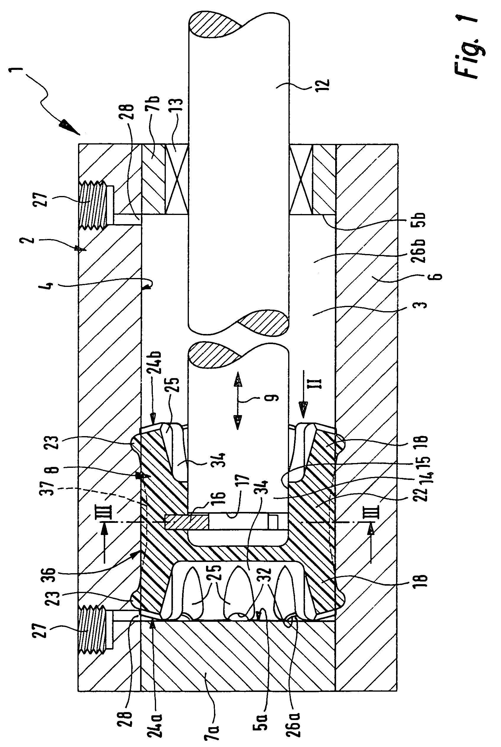
[0026]The power cylinder 1 able to be actuated by fluid power in FIG. 1 is preferably designed for operation using compressed air, though it can be operated with a hydraulic fluid.

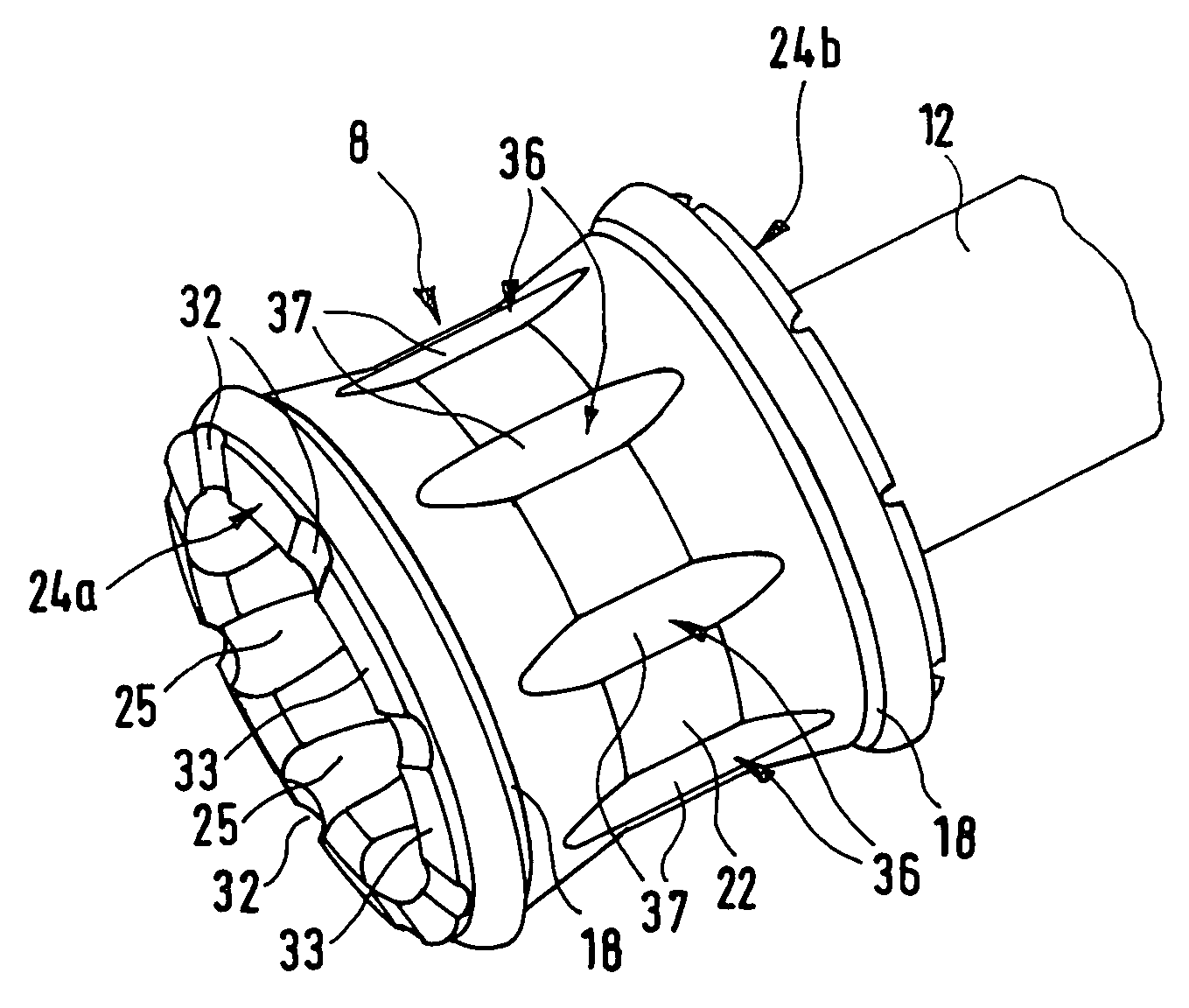
[0027]The power cylinder 1 comprises a cylinder housing 2, which defines an elongated and preferably cylindrically designed piston receiving space 3 which is peripherally delimited by a piston running face 4 on the housing and—at the two ends—a respective axially orientated abutment face 5a and 5b.

[0028]Preferably the cylinder housing 2 is composed of a cylinder barrel 6 defining the piston running face 4 and of two end caps 7a and 7b attached to the cylinder barrel 6 and defining respectively an abutment face 5a and 5b.

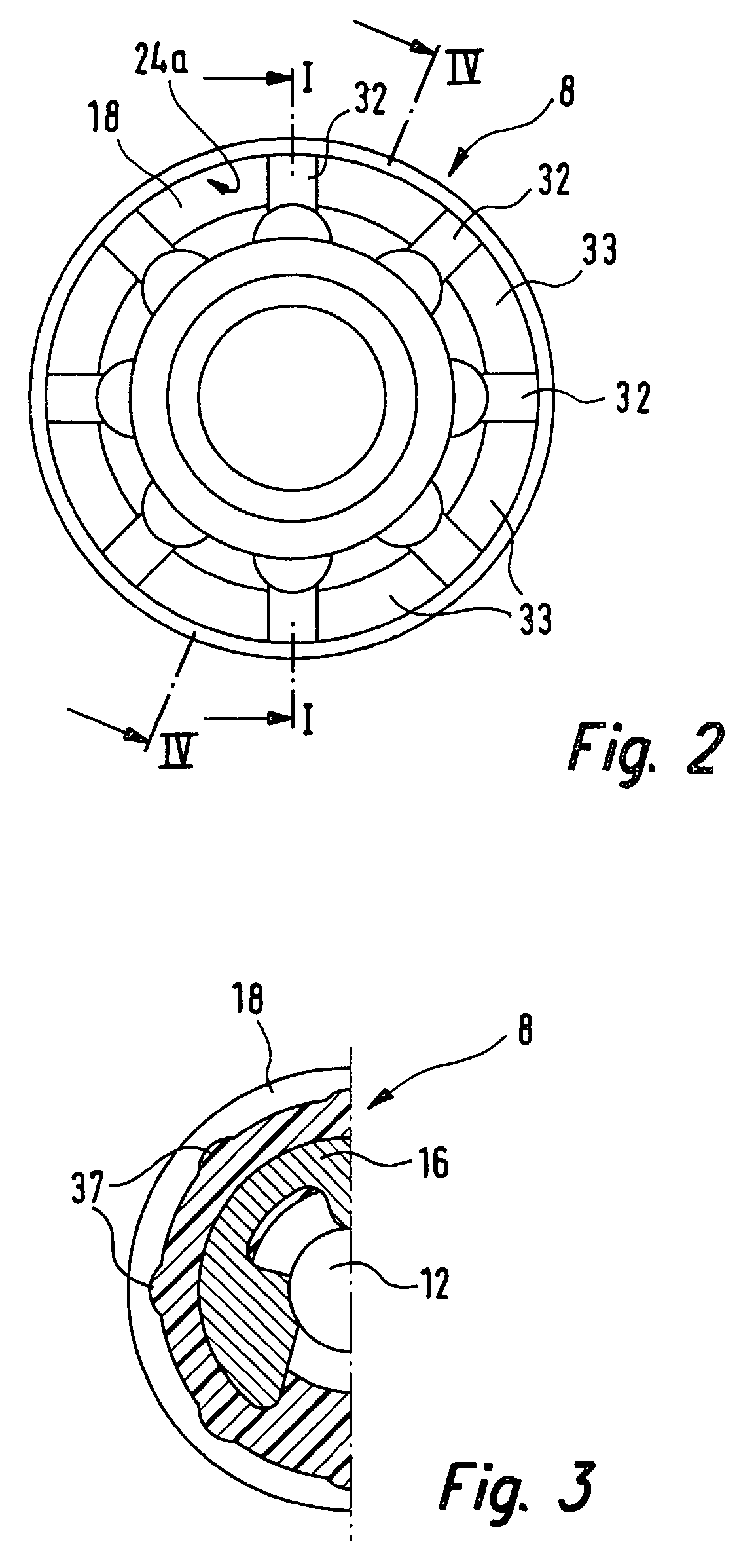
[0029]In the piston running face 3 a piston 8 linearly slides performing a stroke movement 9 indicated by a double arrow. On the piston 8 a piston rod 12 is attached which extends coaxially away from one of the two axially facing sides of the piston, such rod running in a sealing manner t...


PUM


Abstract

A piston for a fluid operated power cylinder has two mutually coaxial sealing lips axially extending away from each other and being able to radially yield, for sealing engagement with the piston running face of the power cylinder and adjacent to at least one piston end side an elastic buffer body serving for shock absorbing in the end of stroke position of the piston, said body having an impact face facing away from the piston. At least at one piston end face the sealing lip itself constitutes the buffer body and has the impact face at its end, groove-like recesses being formed on the inner periphery of the sealing lip with a distribution in the peripheral direction, such recesses opening toward said impact face.

Description

BACKGROUND OF THE INVENTION[0001]The invention relates to a piston for a power cylinder able to be operated by fluid force, comprising two coaxial and radially yielding sealing lips extending axially away from each other and adapted for sealing engagement with the piston engaging face of the power cylinder, and an elastic buffer body arranged in the vicinity of at least one terminal piston face and adapted to serve for impact damping in the end of stroke position of the piston, said buffer body having an impact face turned away from the piston.[0002]Furthermore the invention relates to a power cylinder fitted with such a piston and having a cylinder housing defining a piston receiving space for the piston, said space having a peripheral piston running face and terminal abutment faces.THE PRIOR ART[0003]Such a piston with an associated cylinder is disclosed in the German patent publication 19,925,083 A1. Here the piston is fitted at both its terminal faces with a respective segmented...

Claims


Application Information

Patent Timeline
Patent Type & Authority Patents(United States)
IPC IPC(8): F01B11/02F15B15/22
CPCF15B15/226
Inventor MULLER, GERALD
Owner FESTO AG & CO KG
Why Eureka
Try Eureka