Distributor made of cmc, with stress relief provided by a sealed clamp

Active Publication Date: 2021-04-15
SN DETUDE & DE CONSTR DE MOTEURS DAVIATION S N E C M A
View PDF0 Cites 5 Cited by
  • Summary
  • Abstract
  • Description
  • Claims
  • Application Information

AI Technical Summary

Benefits of technology

The invention proposes a turbine for a turbo engine made of CMC, which makes it easier to mount and allows the parts to deform independently. The CMC material also helps to create a better seal between the nozzle and downstream cavity, ensuring optimal performance of the turbine.

Problems solved by technology

However, the CMC, by its properties very different from metal, is more sensitive to some mechanical stresses.
In addition, the integration of a CMC part into a metallic environment is difficult because of the differential thermal expansions between CMC and metal.
This is all the more difficult in a turbo engine, and more particularly in a high-pressure portion of the turbo engine, because the environment is very hot, which accentuates the differences in the coefficients of thermal expansion between the materials, the aerodynamic forces undergone by a high-pressure nozzle stage being also very high in this turbine area.
However, such a solution takes up both, via the mast, the forces relating to the pressure differential under the nozzle stage and the aerodynamic forces on the CMC crown.
However, such a system does not allow compensating for the relative movements between the parts of the nozzle, and in particular an expansion variation between two tangentially adjacent and not axially adjacent parts, the expansion variation being due to the presence of CMC material at the expansion coefficient lower than that of the metal.

Method used


Image

  • Distributor made of cmc, with stress relief provided by a sealed clamp
  • Distributor made of cmc, with stress relief provided by a sealed clamp
  • Distributor made of cmc, with stress relief provided by a sealed clamp

Examples


Embodiment Construction

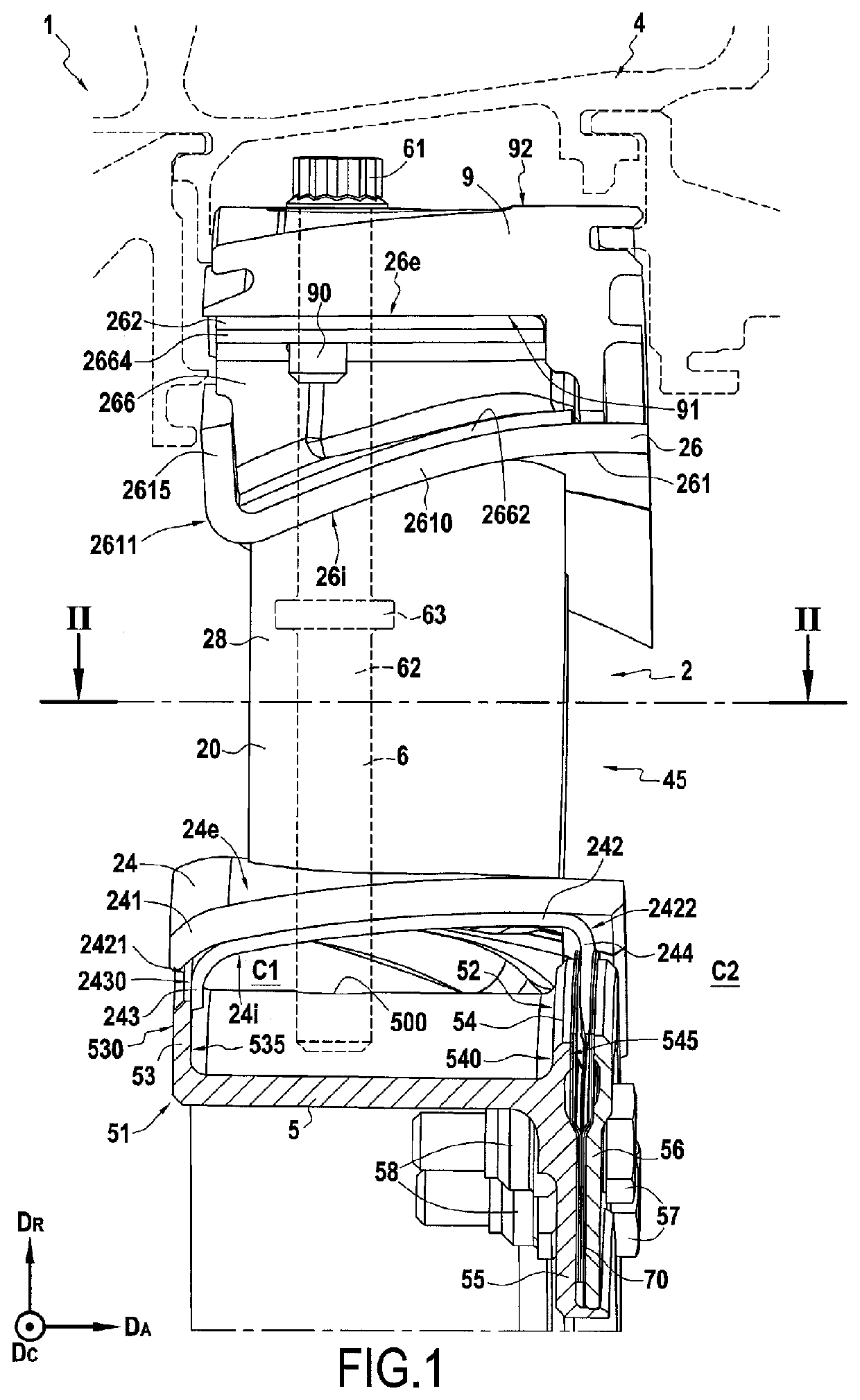
[0069]FIG. 1 illustrates a schematic view of a ring sector of a nozzle stage in a plane defined by the radial direction and the axial direction of the nozzle stage according to a first embodiment of the invention.

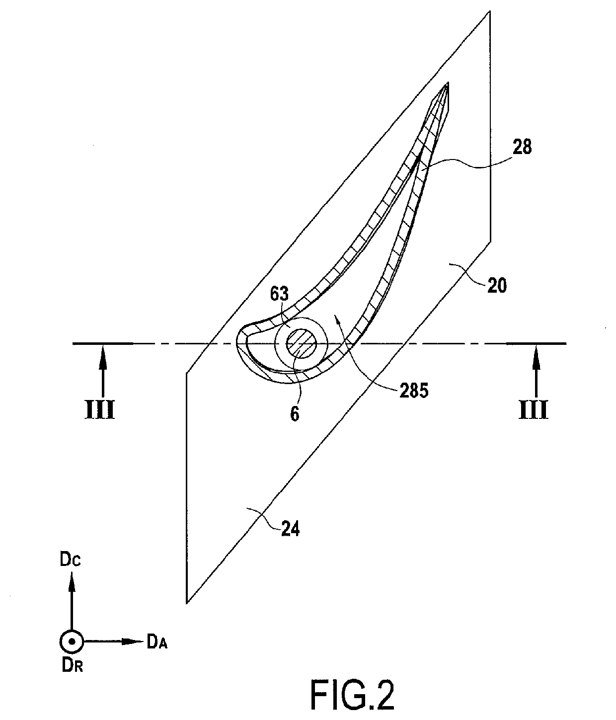
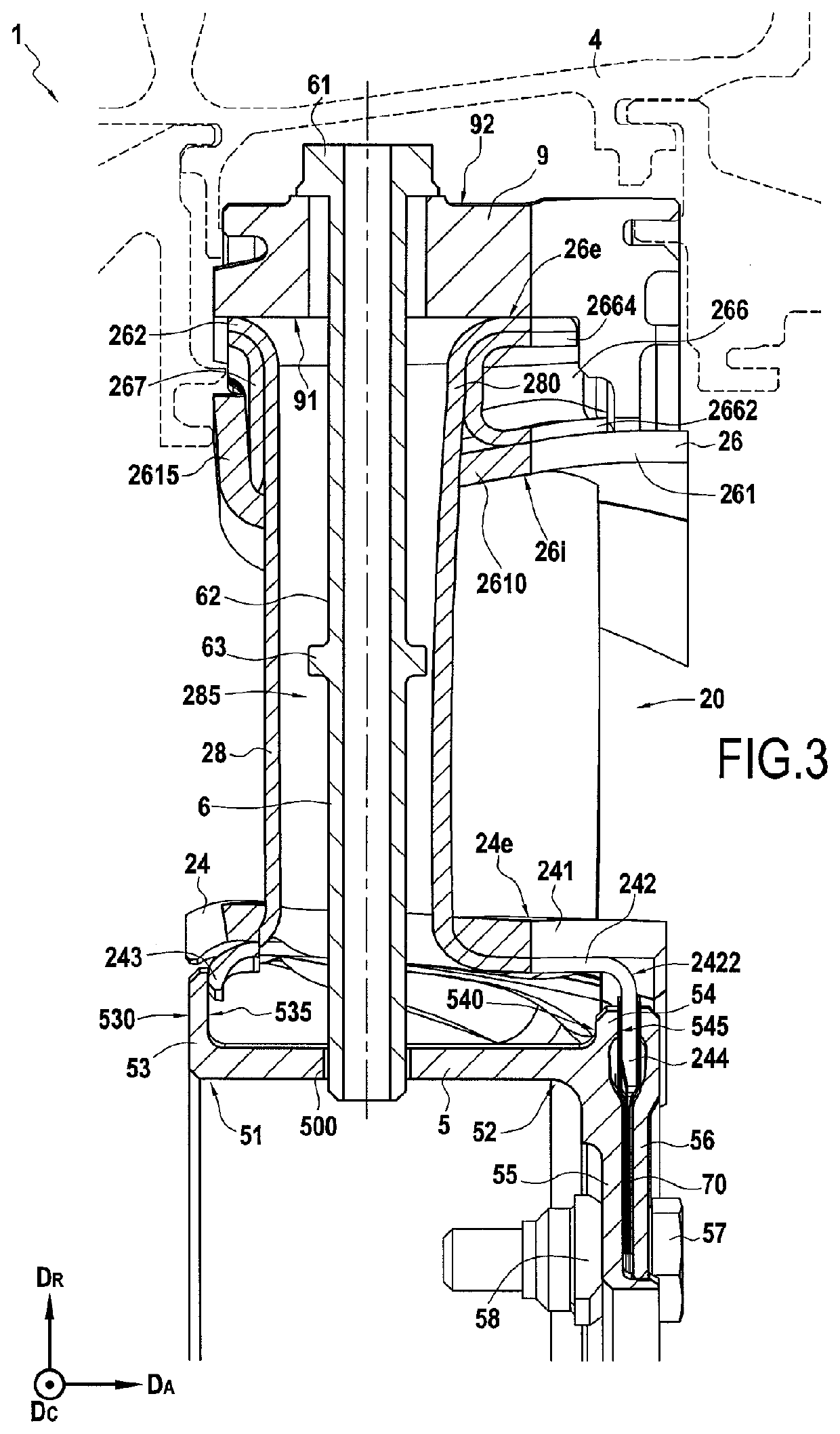
[0070]FIGS. 2 to 4 show respectively a sectional view in a plane defined by the axial direction and the circumferential direction, a schematic sectional view in a plane defined by the radial direction and the axial direction and an exploded schematic view of the ring sector of FIG. 1.

[0071]A high-pressure turbine 1 of a turbo engine, for example an aeronautical turbine engine, as shown partially in FIG. 1, comprises a plurality of fixed nozzle stages 2 which alternate with movable wheels in the flow direction, indicated by an arrow in FIG. 1, of the gas stream F in the turbine 1 and which are mounted in a turbine casing 4.

[0072]Each movable wheel comprises a plurality of vanes having an internal shroud, and at least one blade extending from the internal shroud and linked th...


PUM


Abstract

A turbine of a turbo engine includes a casing and a nozzle stage including an outer metal shroud secured to the casing, an inner metal shroud, and a plurality of ring sectors made of ceramic-matrix composite material each having an internal platform, an external platform and at least one blade extending between the external platform and the internal platform and secured thereto. The internal platform of each sector includes a first and a second tab protruding radially inwardly from respectively an upstream end and a downstream end of the internal platform, and the inner shroud includes a shoulder protruding radially outwardly and being in abutment upstream against the first tab, and a clamp downstream of the shoulder including two jaws extending radially outwardly and held under stress towards each other against the second tab.

Description

BACKGROUND OF THE INVENTION[0001]The invention relates to turbo engines, in particular aeronautical turbine engines or industrial turbines, and more particularly a turbine nozzle stage made of ceramic-matrix or at least partially ceramic-matrix composite material, hereinafter referred to as CMC material.[0002]The field of application of the invention is in particular that of aeronautical gas turbine engines. The invention is however applicable to other turbo engines, for example industrial turbines.[0003]The improvement of the performances of turbo engines and the reduction of their pollutant emissions leads to consider increasingly higher operating temperatures.[0004]For elements of hot portions of turbo engines, it has therefore been proposed to use ceramic-matrix composite materials noted CMC thereafter.[0005]The CMC materials are typically formed from a fibrous reinforcement made of refractory fibers, such as carbon or ceramic fibers, densified by a ceramic or at least partially...

Claims


Application Information

Patent Timeline
IPC IPC(8): F01D9/04F01D5/28F01D5/18
CPCF01D9/042F01D5/282F01D9/041F05D2300/6033F05D2240/128F05D2260/31F01D5/18F01D5/284F01D25/246Y02T50/60
Inventor JARROSSAY, CLÉMENTCONGRATEL, SÉBASTIEN SERGE FRANCISDANIS, ANTOINE CLAUDE MICHEL ETIENNEDUFFAU, CLÉMENT JEAN PIERREQUENNEHEN, LUCIEN HENRI JACQUES
Owner SN DETUDE & DE CONSTR DE MOTEURS DAVIATION S N E C M A
Why Eureka
Try Eureka