
Continuous cable processing apparatus

a processing apparatus and cable technology, applied in the direction of cable installation apparatus, electrical equipment, other manufacturing equipment/tools, etc., can solve the problems of inability to use processing stations, inability to provide short cable sections, and associated with additional costs, so as to reduce the processing time of individual steps

Inactive Publication Date: 2005-03-10
SCHLEUNIGER HLDG
View PDF3 Cites 52 Cited by
  • Summary
  • Abstract
  • Description
  • Claims
  • Application Information

AI Technical Summary

Benefits of technology

[0034] If it is intended to strip a long piece of insulation in a few individual steps, this can be carried out according to the invention by opening the second pair of rollers or pair of belts in each partial step. Compared with the known apparatus (e.g. KODERA Type 36 with a particularly large distance between the left and the right feed rollers), there is the advantage that even short cable sections can be stripped of insulation. Compared with the known apparatus (e.g. KODERA Type 34 with a relatively small distance between the left and right feed rollers), there is on the other hand the advantage of virtually any desired insulation stripping length and absolutely no limitation to the distance between tool holder and second, axially following pair of rollers, which to date limited the insulation stripping distance in all known machines.
[0035] Regarding the second variant: Apart from the cable processing in the (specific) knife station, the use of further processing sta...

Problems solved by technology

This type of end processing establishes the processing times. However, a disadvantage with attachments involving such processing in a working area into which various processing tools or processing stations can be inserted is that it is not possible to use processing stations which are longer than the distance between the transport means on both sides of the knife station.
On the other hand, however, this distance should not be too large because otherwise short cable sections cannot be provided.
Moreover, with a large distance, a further guide element would have to be used between the receiving region of the processing station and the transport means, which is associated with an additional cost.
This has an advantage over a single knife position; at the same time, however, the disadvantage of this design in practice is the limitation of possible processing operations, which are restricted to the two knife positions.
A disadvantage of this means is that the two cable handling components (before and after the knife) constantly have to be displaced in the longitudinal and transverse direction, leading to considerable wear of two components highly mobile essentially independently of one another (in addition to the axial feed drive for the cable).
In addition, the use of a multiblade knife is uneconomical since nonuniform wear may occur and it may therefore also be necessary to replace blades which are not worn.
Moreover, this apparatus requires particular flexibility of the cable, which is otherwise liable to be destroyed.
This apparatus is not suitable for automatic insulation stripping operations.
The problem of cable flexibility occurs here too.
Moreover, the cable does not rest optimally perpendicular to the plane of the knife in this apparatus, so that cuts by the knife may also be performed obliquely, with the result that the cuts may be of poor quality, unless the second knife is positioned obliquely relative to the first one.
However, such an oblique position described by the EP A1 has the disadvantage that it is optimized only for specific knives; in addition, it broadens the attachment of the knife supports.
The disadvantage of such an arrangement is a relatively low flexibility in the choice of the processing steps; moreover, the limited space between the knives restricts the possible insulation stripping length.
The Kodera Type 36 with a greater distance between insulation stripping knives and second pair of rollers was provided to permit longer partial insulation stripping steps but had the disadvantage that short cable pieces could not be stripped with this apparatus.
A further problem is that thin flexible cables cannot be concentrically guided in the case of the guides with rigid inner diameters mounted in the known apparatuses, e.g. Eubanks 9800, which may lead to problems (more frequent breakdowns) in the cable feed.
Problems also arise in the ejection of the waste (slug) of insulation residues which are stripped from the conductor by the knife and, from case to case, were not properly removed to date, since they sometimes stuck to the conductor and thus led to breakdowns.
As is clearly evident in FIG. 5 of this US patent, however, buckling of the cable end piece occurs.
None of the known continuous cable processing apparatuses thus offers possibilities for removing a cable from its present transport path without buckling or bending, in order to transport it to another processing station, a manipulator arm or merely to another knife within this knife station.
In the case of specific cable types, this leads to considerable problems and thus restricts the universality of the relevant apparatuses.
JP-A-3-15211 describes a cable end processing apparatus which permits buckling- and bending-free transportation of a cable end from one processing station to another one, but continuous cable processing is not possible therewith since secondary transport means are lacking and it was evidently also not obvious to propose such means by appropriate complicated structural conversions.
However, longitudinal feeding of the cable by these known attachments is not known.
If, as disclosed in the prior art, the contact pressure were to remain constant over the entire process, this would have the disadvantage that the cable or its sheath would suffer pinches over its entire length, which now occur at most in a small region.

Method used


Image

  • Continuous cable processing apparatus
  • Continuous cable processing apparatus
  • Continuous cable processing apparatus

Examples


Embodiment Construction

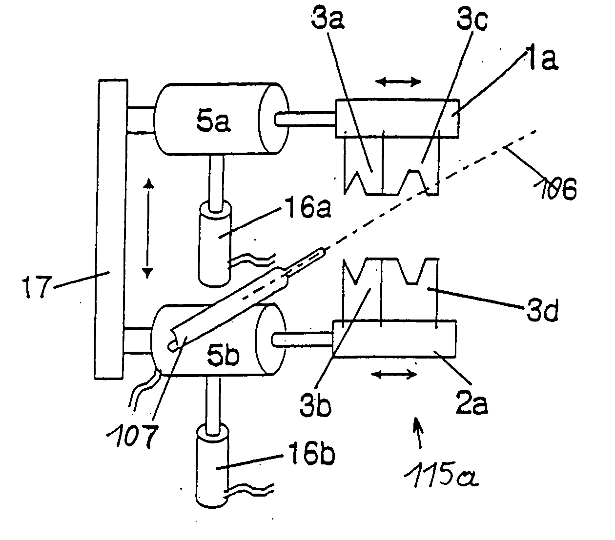
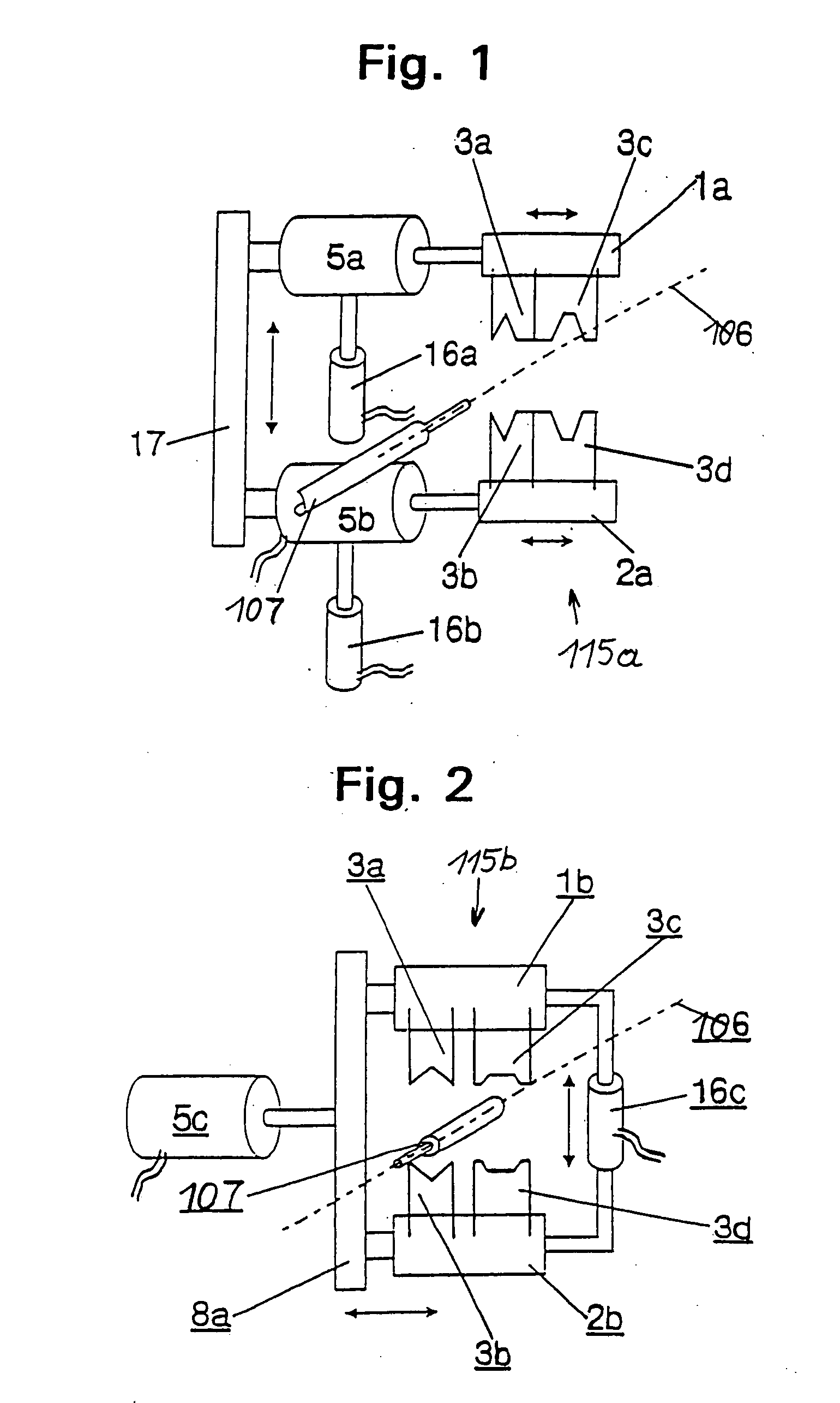
[0075]FIG. 1 shows a schematic oblique view of a novel apparatus according to the invention, having tool supports 1, 2 and knives 3 which are held thereon and a plurality of which (more than the 2 pairs shown) may be mounted side by side on larger tool supports 1, 2. Schematically shown drives 5a and 5b drive the tool supports laterally relative to the axis 106. Schematic closing drives 16a and 16b enable the tool holders 1, 2 to be closed together (via a control) or separately. A guide 17 keeps the tool supports or tool holders and the drives parallel.

[0076]FIG. 2 shows a variant thereof having upper and lower tool holders 1, 2 jointly guided via a closing drive 16c, for example by means of a spindle drive and a single lateral drive 5c. This simplified variant is compact but—in comparison with the first one—permits only a few operations.

[0077] Both above-mentioned Figures refer to an important aspect of the invention, namely the virtually completely free mobility of at least one ...


PUM

PropertyMeasurementUnit
Timeaaaaaaaaaa
Lengthaaaaaaaaaa
Forceaaaaaaaaaa

Abstract

A continuous cable processing apparatus for producing cable sections with processed ends comprises a cable transport apparatus having at least one transport means for moving and holding the cable in the axial direction and, transversely thereto, a knife station. According to a special variant, two transport means are arranged in the longitudinal cable direction on both sides of the knife station and, after the cable has been cut through, each hold one of the cable end regions produced on cutting, so that said end regions are movable in the longitudinal cable direction. At least one of these end processing stations is arranged transversely with respect to the longitudinal cable direction, adjacent to the knife station and at least one transport means is movable transversely with respect to the longitudinal cable direction so that a cable end region can be fed to the end processing station.

Description

CROSS-REFERENCE TO RELATED APPLICATIONS [0001] This Divisional Application of U.S. patent application Ser. No. 09 / 068,278 is filed under 35 USC 111 claiming priority benefits of U.S. patent application Ser. No. 09 / 068,278 under 35 USC 120. U.S. patent application Ser. No. 09 / 068,278 (now allowed) entered the national stage under 35 USC 371 on Jul. 9, 1998, and is PCT / EP97 / 05216, filed on Sep. 23, 1997. PCT / EP97 / 05216 claims priority under 35 USC 119 to Swiss Application CH 2329 / 96, filed on Sep. 23, 1996. PCT / EP97 / 05216 (and hence, U.S. patent application Ser. No. 09 / 068,278) is a Continuation in Part Application of PCT / EP96 / 04790, filed Nov. 4, 1996, which claims priority under 35 USC 119 of Swiss Application CH 3235 / 95, filed on Nov. 6, 1995. Thus, the present Continuation Application of U.S. patent application Ser. No. 09 / 068,278 also claims priority of Swiss Application CH 3235 / 95.STATEMENT REGARDING FEDERALLY SPONSORED RESEARCH OR DEVELOPMENT [0002] Not applicable. BACKGROUND O...

Claims


Application Information

Patent Timeline
IPC IPC(8): H01R43/05H01R43/052H02G1/12
CPCH01R43/05H01R43/052H01R43/28H02G1/005Y10T29/5187H02G1/1268Y10T29/514Y10T29/53213Y10T29/5193H02G1/1256
Inventor LOCHER, BEATSTEPAN, JIRI
Owner SCHLEUNIGER HLDG
Learn More