Exhaust gas purification device of engine for vehicle

a technology of exhaust gas purification device and engine, which is applied in the direction of exhaust treatment electric control, electrical control, separation process, etc., can solve the problems of deteriorating the durability of the particulate filter, the temperature of the particulate filer may increase too quickly, and the start feeling of the vehicle driver is affected, so as to avoid any disadvantages of fuel efficiency and the start feeling of the vehicle, the effect of rapid temperature increas

Inactive Publication Date: 2005-03-10
MAZDA MOTOR CORP
View PDF4 Cites 42 Cited by
  • Summary
  • Abstract
  • Description
  • Claims
  • Application Information

AI Technical Summary

Benefits of technology

[0009] The present invention has been devised in view of the above-described problems, and an object of the present invention is to provide an exhaust gas purification device of an engine for a vehicle which can suppress deterioration of the durability of a filter member due to its rapid temperature increasing, avoiding any disadvantages of a fuel efficiency and a start feeling of the vehicle.

Problems solved by technology

Herein, the above-described regeneration control is configured such that when it is determined that the state of the vehicle changes from the stop state to a driving state by detecting, for example, pressing of an accelerator pedal (so-called racing operation), or changing of shift range from its stop ranges (P range, N range) to its driving range (D range), the engine speed is so controlled as to return (decrease) to its specified normal idle speed, not to the above-described raised higher speed, because raising the engine speed to such higher speed may cause some problems in a start feeling for a vehicle driver.
However, the inventors of the present invention found out another problem that if the engine speed which has been raised once is returned to its specified normal idle speed soon after the above-described driver's intention to start the vehicle is detected during the regeneration of the particulate filter, the temperature of the particulate filer may increase too rapidly, thereby deteriorating the durability of the particulate filter.
As a result, the temperature of the particulate filter may increase too rapidly.
However, there may occur further another problem of an improper fuel efficiency if the above-described engine speed control that the engine speed is returned to the specified engine speed slightly higher than the specified normal idle speed is always performed regardless of the temperature of the particulate filter.
Namely, in the event that the temperature of the filter member is relatively low and thereby an improper influence of the above-described temperature increasing of particular filter is small, such controlling of the engine speed to the specified engine speed slightly higher than the specified normal idle speed may deteriorate the fuel efficiency.

Method used


Image

  • Exhaust gas purification device of engine for vehicle
  • Exhaust gas purification device of engine for vehicle
  • Exhaust gas purification device of engine for vehicle

Examples


embodiment 1

[0046] EMBODIMENT 1

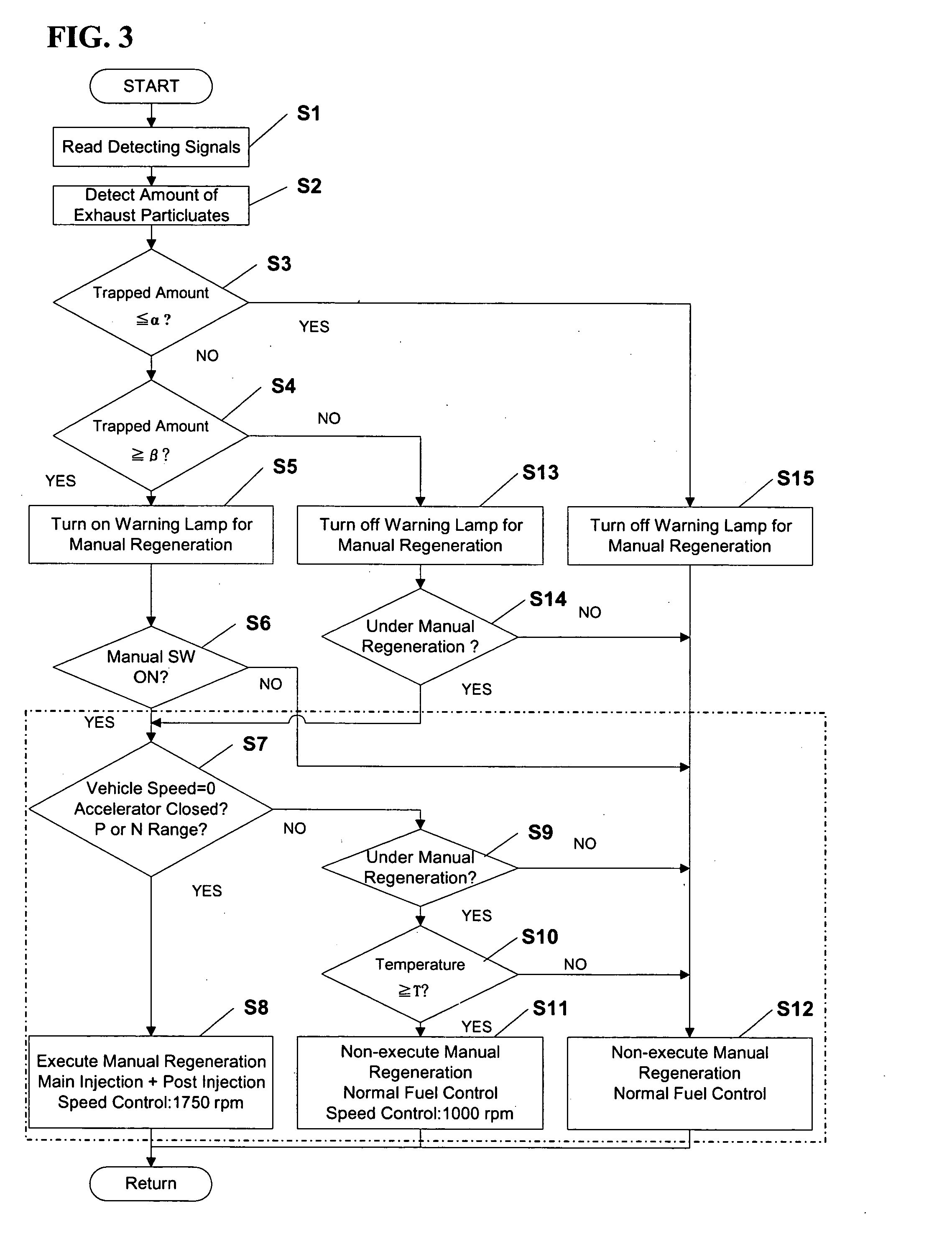
[0047] Next, a manually operated regeneration control for the particulate filter 12 according to a first embodiment will be described referring to a flowchart of FIG. 3.

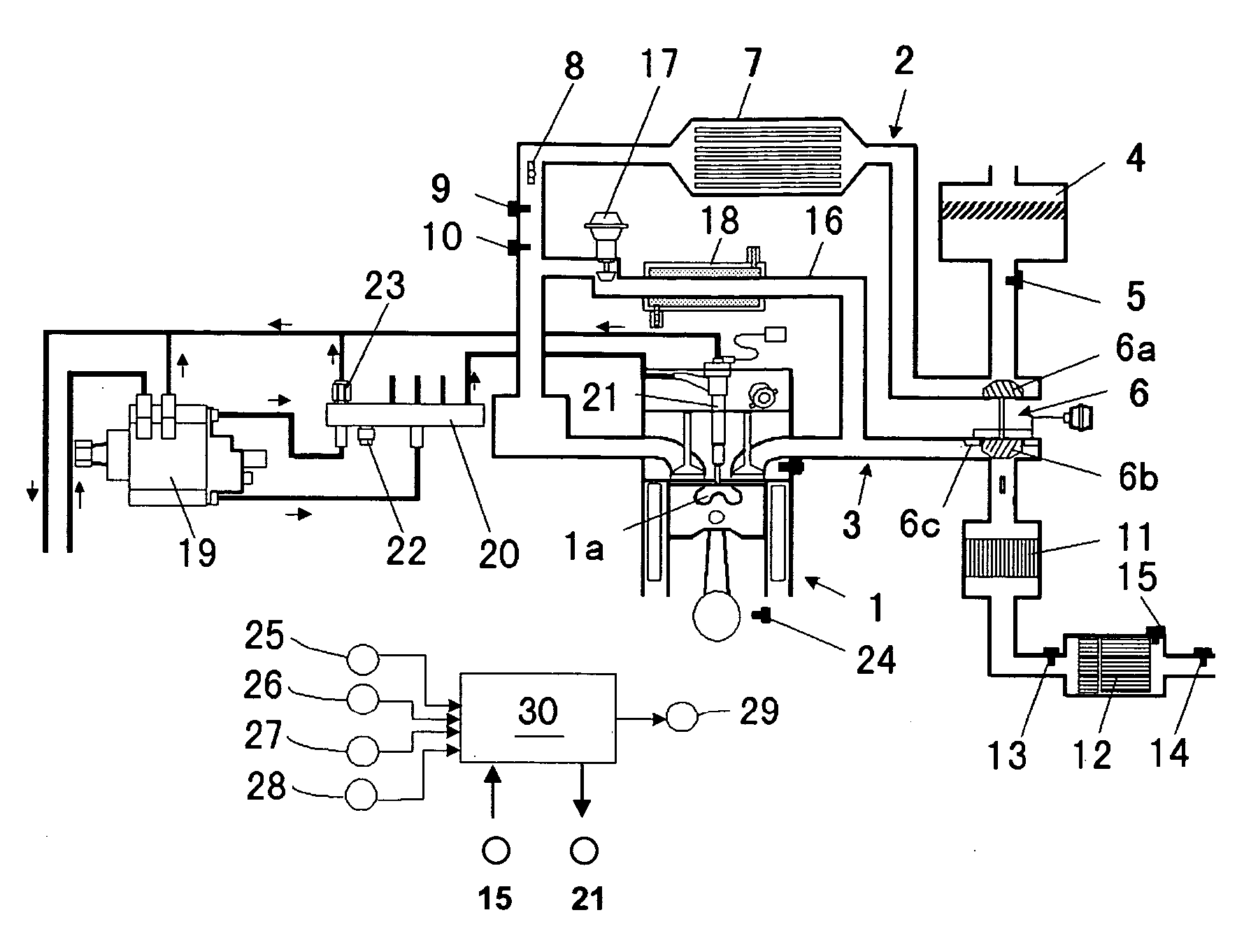
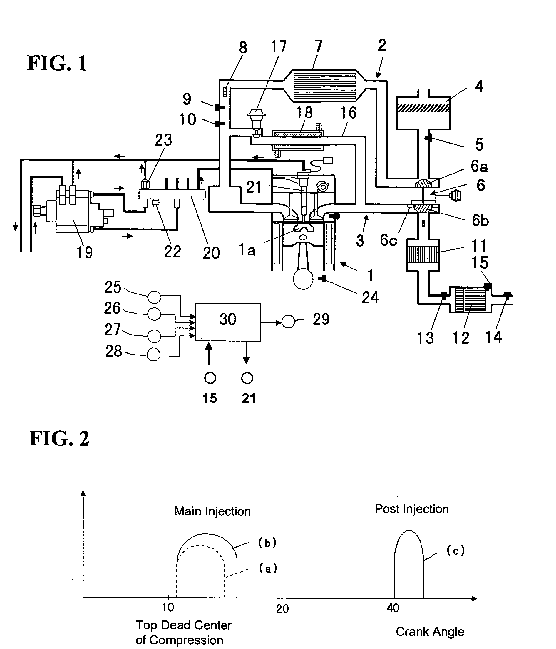
[0048] In step S1 of FIG. 3, respective detection signals from the exhaust pressure sensors 13, 14, temperature sensor 15, crank angle sensor 24, vehicle speed sensor 25, accelerator sensor 26, range position detecting sensor 27 and manual regeneration switch 28 are read in.

[0049] Subsequently, in step S2, the amount of exhaust particulates trapped by the particulate filter 12 is detected based on the pressure difference according to the exhaust pressure sensors 13, 14. Namely, according to increasing of the trapped particulates, the pressure of the exhaust gas upstream of the particulate filter 12 increases and thereby the above-described pressure difference becomes greater. Accordingly, the amount of exhaust particulates trapped by the particulate filter 12 can be detected based on the pressure...

embodiment 2

[0069] EMBODIMENT 2

[0070] Next, the manual regeneration control of the particulate filter 12 according to a second embodiment will be described referring to FIGS. 5 and 6.

[0071] The first embodiment described above describes an example in which the determination as to which one of the second target speed and the normal idle speed for non-regeneration is selected when the shift range position is shifted from P or N range to D range is made based on the temperature of the particulate filter 12 detected directly by the temperature sensor 15. The second embodiment, however, describes an example in which the temperature of the particulate filter 12 is detected indirectly (presumed) based on a lapse of time from the commencement of manual regeneration, instead of detecting the temperature directly, and thereby the determination as to which one of the above speeds is selected is made.

[0072]FIG. 5 shows only part of flowchart according to the second embodiment which is different from that...


PUM

PropertyMeasurementUnit
temperatureaaaaaaaaaa
speedaaaaaaaaaa

Abstract

There are provided a particulate filter and a manual regeneration switch. When the manual regeneration switch is operated and the vehicle is in a stop state, the engine speed is adjusted to a first target higher than a normal idle speed to regenerate the filter. Meanwhile, when the vehicle changes from its stop state to its driving state, the engine speed is adjusted to a second target higher than the normal idle speed but lower than the first target in the event that the temperature of the filter is high, while the engine speed is adjusted to the normal idle speed in the event that the temperature of the filter is low. Accordingly, deterioration of the durability of the filter due to its rapid temperature increasing can be suppressed, avoiding disadvantages of fuel efficiency and vehicle start feeling.

Description

BACKGROUND OF THE INVENTION [0001] The present invention relates to an exhaust gas purification device of an engine for a vehicle, and more particularly, to an exhaust gas purification device of an engine for a vehicle which comprises a filter member disposed in an exhaust passage of the engine to trap exhaust particulates in an exhaust gas. [0002] Conventionally, for example, a diesel engine is equipped with a filter member, so-called a particulate filter, which is disposed in an exhaust passage so as not to emit exhaust particulates of carbon or the like in its exhaust gas to an atmosphere. [0003] In the engine with such a particulate filter, it is required to burn trapped particulates by the particulate filter and thereby regenerate the filter when the amount of tapped particulates has reached to a maximum value to be trapped at the filter. Accordingly, for example, Japanese Patent Laid-Open Publication No. 4-86319 discloses a device in which there is provided a manual switch ope...

Claims


Application Information

Patent Timeline
Patent Type & Authority Applications(United States)
IPC IPC(8): B01D46/44F01N3/02F01N3/021F01N3/023F01N3/025F01N3/029F01N3/035F01N3/24F01N3/36F01N9/00F01N13/02F02B37/24F02D31/00F02D41/02F02D41/08F02D41/38
CPCF01N3/035F01N13/009F01N2560/08F01N2560/14F02B37/24F02D31/001F02D41/0225F02D41/029F02D41/08F02D2041/0265F02D2200/0802F02D2200/0812F02D2200/502Y02T10/144F01N2560/06F01N3/0238F02D41/405F02D41/025F02D2200/604F02D41/0245Y02T10/12
Inventor NISHIMURA, HIROYUKI
Owner MAZDA MOTOR CORP
Why Eureka
Try Eureka