Castable three-dimensional stationary phase for electric field-driven applications

a three-dimensional stationary phase and electric field technology, applied in the field of microfluidic devices, to achieve the effect of high internal volume, small pores and easy controllability

Inactive Publication Date: 2005-03-10
NAT TECH & ENG SOLUTIONS OF SANDIA LLC
View PDF2 Cites 2 Cited by
  • Summary
  • Abstract
  • Description
  • Claims
  • Application Information

AI Technical Summary

Benefits of technology

In contrast to prior art phase separation polymerization processes, an inverse emulsion polymerization process provides an easily controllable method for producing a polymer material having characteristics that are particularly desirable for stationary phase materials for electric field-driven applications and, in particular, as the dielectric medium for electrokinetic pumps. The polymer material comprising a 3-dimensional polymer network characterized by small pores and high internal volume, can also be used as a passive mechanical support structure, wherein a low viscosity monomer can be diffused into the porous structure to provide a dielectric material for electrokinetic pump applications. The use of bifunctional monomers provides a plurality of charged sites within the polymer structure, thereby making this material suitable as the stationary phase for applications using electroosmotic flow particularly in non-silica columns, and for binding the 3-dimensional polymeric material to the walls of the microchannels, thereby making it suitable for high pressure applications, such as could be encountered in electrokinetic pump applications. Moreover, since the aqueous phase that forms the structure of the inverse emulsion is conductive it can be easily exchanged for other aqueous phases using electroosmotic flow, thereby eliminating the need for high pressure pumping. The inventive polymer material has also been shown to be stable over a pH range of 1-12.

Problems solved by technology

In addition, problems associated with the production of cast-to-shape polymeric stationary phase materials in microchannels and removal of solvents are solved.

Method used


Image

  • Castable three-dimensional stationary phase for electric field-driven applications
  • Castable three-dimensional stationary phase for electric field-driven applications
  • Castable three-dimensional stationary phase for electric field-driven applications

Examples


Embodiment Construction

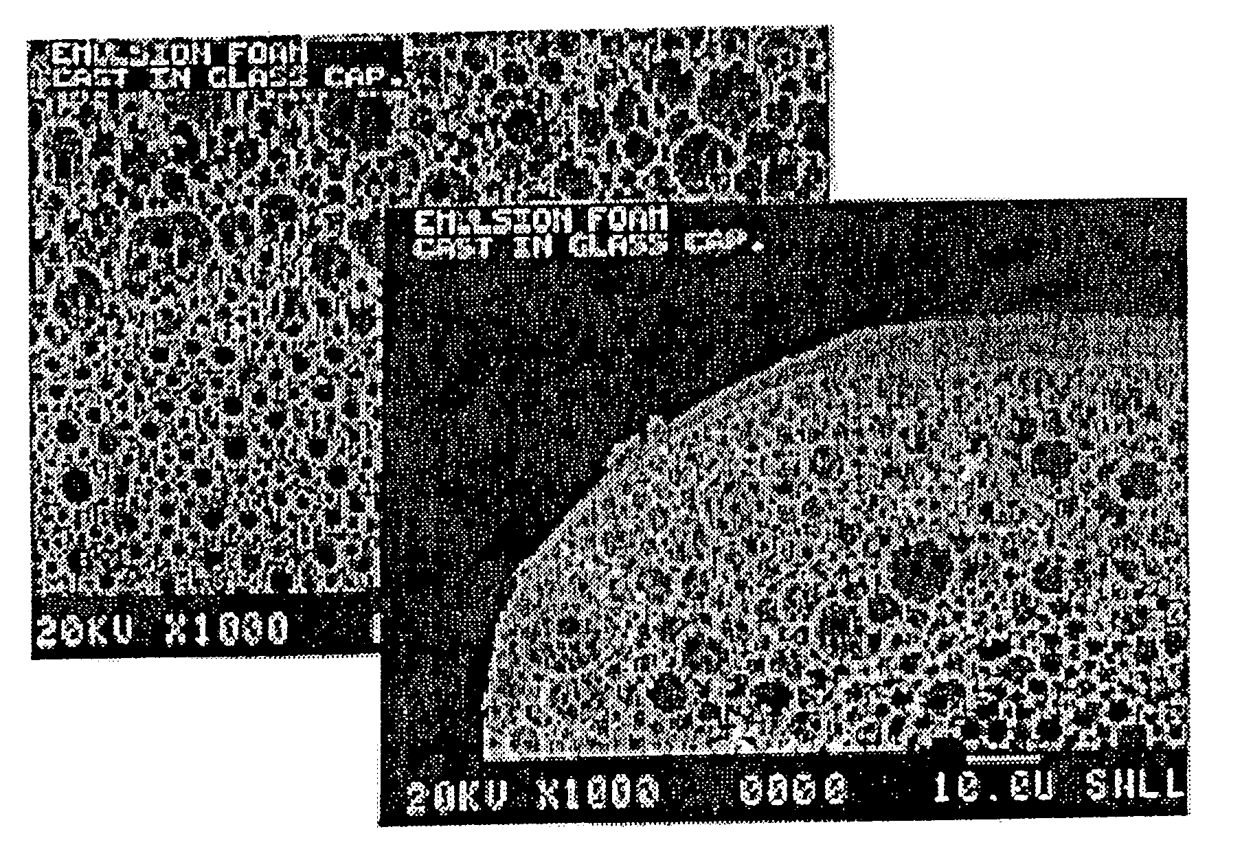
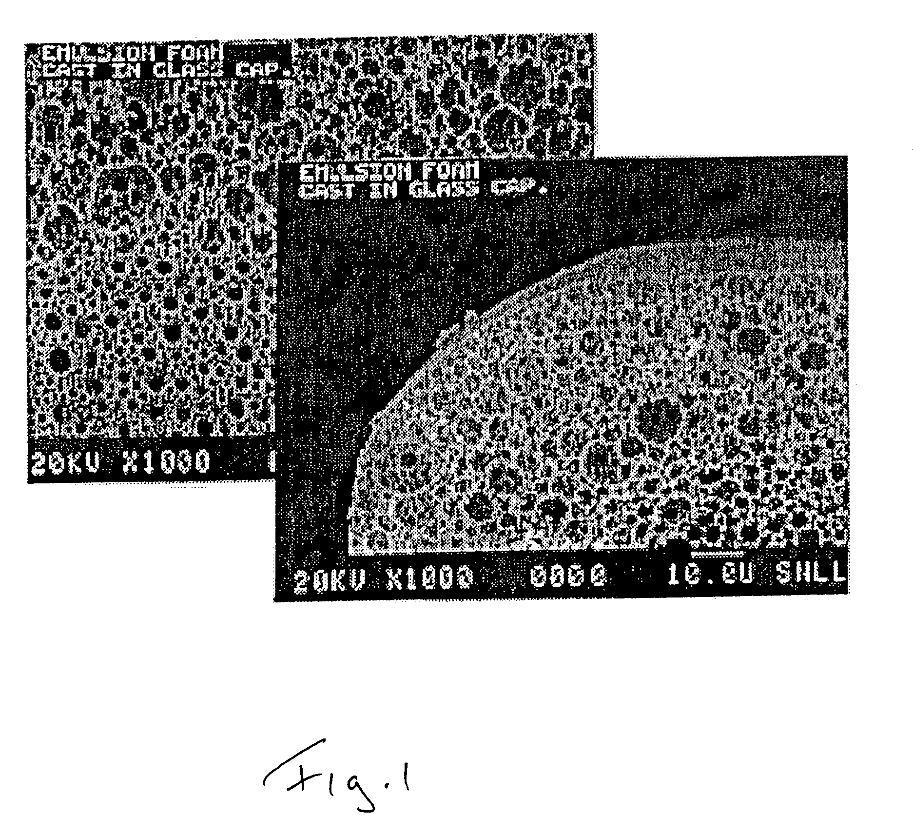
The present invention is directed to microfluid devices that employ electroosmotic flow for applications such as capillary electrochromatography and capillary zone electrophoresis, and particularly electrokinetic pumping and thus, have at least one fluid flow channel that has a stationary phase or porous dielectric material disposed therein. In this invention, that material comprises a 3-dimensional polymer material that can be cast-to-shape inside a capillary tube, microchannel, or a micromachined groove to form a material that possesses unique features that makes it especially suitable as a stationary phase for these electric field-driven applications. Included among these features are: 1) an interconnected 3-dimensional network of organic struts that provide a high internal volume and surface area and can also act as a framework for infusion of a low viscosity monomer that can be subsequently polymerized in place to support electroosmotic flow (see FIG. 1); 2) a surface that can...


PUM

PropertyMeasurementUnit
acidic or basicaaaaaaaaaa
structureaaaaaaaaaa
temperatureaaaaaaaaaa

Abstract

A polymer material useful as the porous dielectric medium for microfluidic devices generally and electrokinetic pumps in particular. The polymer material is produced from an inverse (water-in-oil) emulsion that creates a 3-dimensional network characterized by small pores and high internal volume, characteristics that are particularly desirable for the dielectric medium for electrokinetic pumps. Further, the material can be cast-to-shape inside a microchannel. The use of bifunctional monomers provides for charge density within the polymer structure sufficient to support electroosmotic flow. The 3-dimensional polymeric material can also be covalently bound to the channel walls thereby making it suitable for high-pressure applications.

Description

BACKGROUND OF THE INVENTION This invention is directed generally to microfluidic devices that employ electroosmotic flow, and particularly electrokinetic pumps, having flow channels that contain a stationary phase or porous dielectric material prepared by an inverse emulsion method that imparts desirable structure and properties. Monolithic polymeric materials composed of polymerized monomers (styrenes, acrylates, methacrylates, etc.) have proven useful as the stationary phase for various chromatographic applications and particularly for applications involving miniaturized or capillary columns where traditional methods of column packing have proven to be ineffective. Polymer materials are among the class of materials that have been found to be useful for electric field-driven applications and particularly as porous dielectric media for electrokinetic pump applications. Porous stationary phase materials that are “cast-in-place” or “cast-to-shape” by phase-separation polymerization ...

Claims


Application Information

Patent Timeline
Patent Type & Authority Applications(United States)
IPC IPC(8): G01N27/447
CPCG01N27/44747
Inventor SHEPODD, TIMOTHY J.WHINNERY, LEROY JR.EVEN, WILLIAM R. JR.
Owner NAT TECH & ENG SOLUTIONS OF SANDIA LLC
Why Eureka
Try Eureka