
Vehicular brake control device

a technology of brake control and brake lever, which is applied in the direction of brake components, vehicle components, braking systems, etc., can solve the problems of high slip ratio, high target slip ratio, and increased slip ratio

Inactive Publication Date: 2005-03-10
ADVICS CO LTD
View PDF0 Cites 7 Cited by
  • Summary
  • Abstract
  • Description
  • Claims
  • Application Information

AI Technical Summary

Benefits of technology

[0007] An object of the present invention is to provide a vehicular brake control device in which even if granular objects are sprinkled between tires and the road surface during the ABS control, the effect of the reduction in the braking distance is maintained.
[0011] Thus, when the wheels having the large slip ratio, or the locked wheels ride on the granular objects sprinkled on the road surface, the granular objects are sandwiched between the wheels and the road surface. The friction coefficient between the wheels and the road surface is increased by the spike effect. Accordingly, the braking distance of the vehicle is further reduced.
[0017] According to the present invention, the granular objects are sprinkled to the left and right front wheels only, and the target slip ratio is increased in correspondence with sprinkling of the granular objects. Thus, the friction coefficient between the left and right front wheels and the road surface is increased by the spike effect of the granular objects. Therefore, the strong braking force is generated by the left and right front wheels, and the effect of the reduction in the braking distance is achieved. By distributing the braking force to the front wheels and rear wheels, stability of the vehicle is achieved.
[0019] According to the present invention, the granular object sprinkling device is operated to sprinkle the granular objects to the left and right front wheels, and, at the same time, the target slip ratio in the ABS control is changed to the relatively large second value for the left and right front wheels only. Thus, a large braking force is generated at the left and right front wheels, and the effect of the reduction in the braking distance is achieved. Since the normal ABS control is performed using the relatively small first value for the left and right rear wheels, the slip ratio of the left and right rear wheels is not increased. Thus, stability of the vehicle is achieved.

Problems solved by technology

Therefore, the rotational speeds of the wheels are likely to be lowered (the slip ratio is likely to be increased), and locking is likely to occur.

Method used


Image

  • Vehicular brake control device
  • Vehicular brake control device
  • Vehicular brake control device

Examples


first embodiment

[0032] First Embodiment

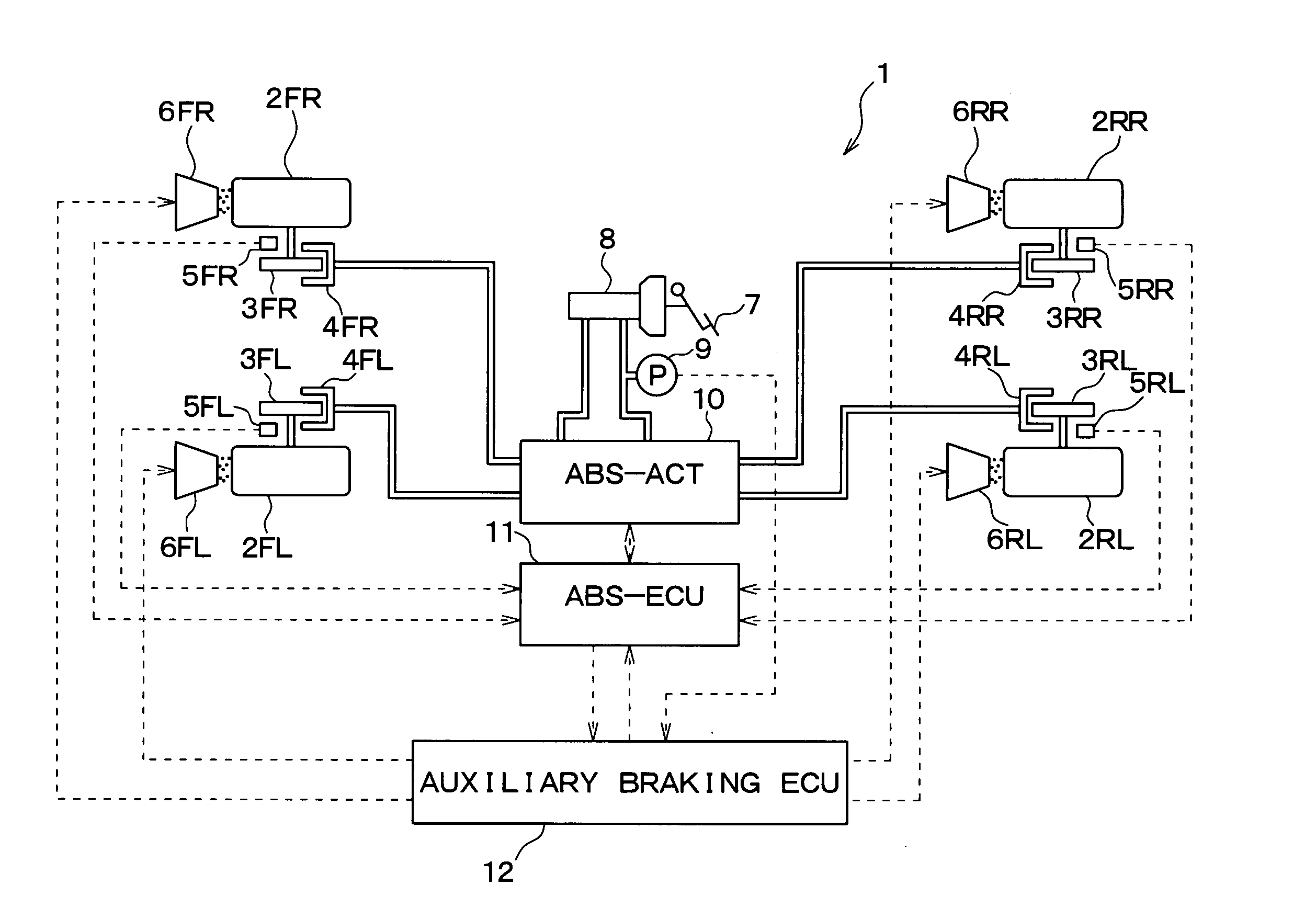
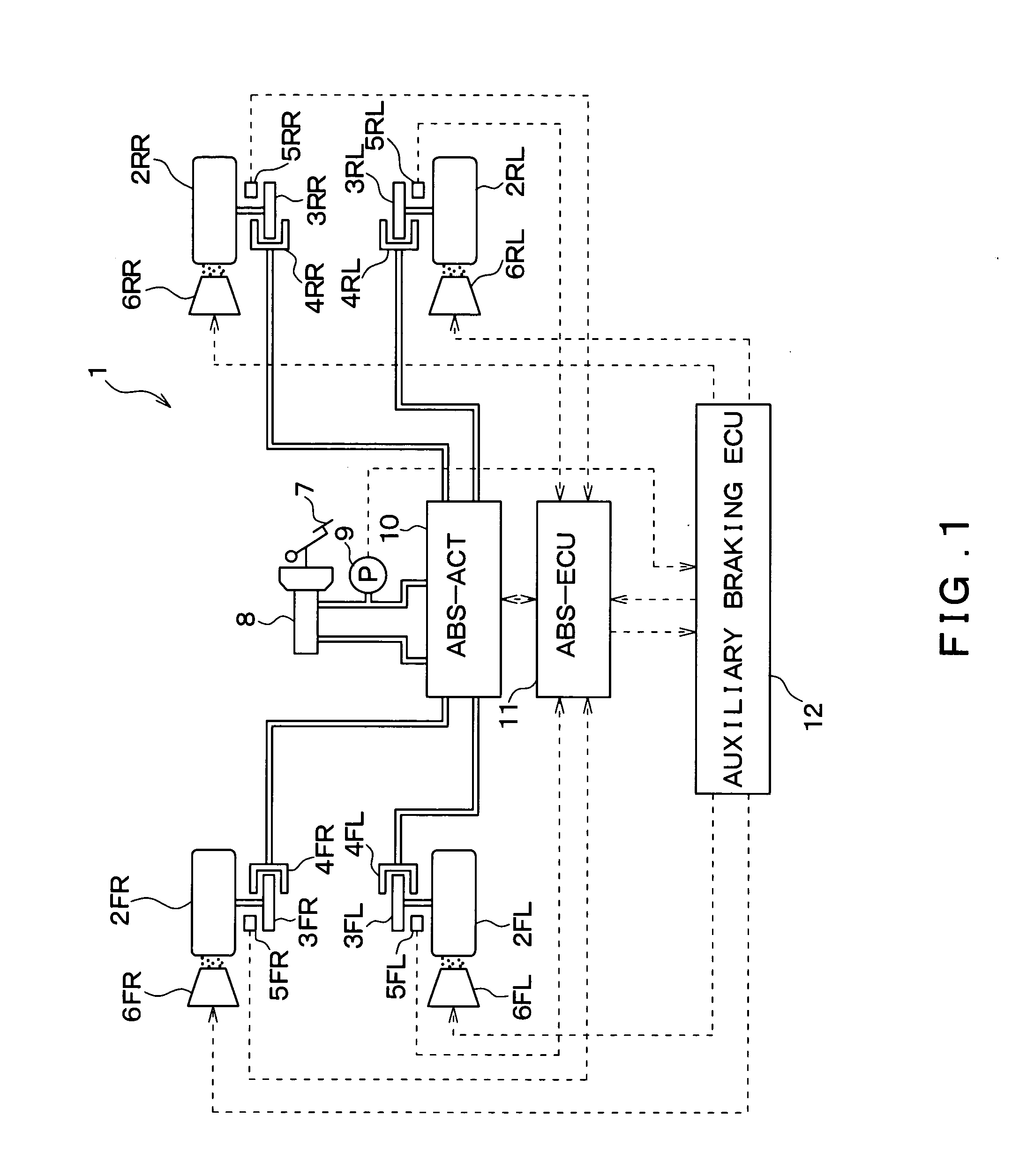
[0033] Hereinafter, a first embodiment of the present invention will be described with reference to drawings. FIG. 1 is a diagram schematically showing an overall structure of a vehicle 1 to which a vehicular brake control device according to the first embodiment of the present invention is applied.

[0034] The vehicle 1 includes a left front wheel 2FL, a right front wheel 2FR, a left rear wheel 2RL, and a right rear wheel 2RR. Disk rotors 3FL-3RR, wheel cylinders (hereinafter referred to as “W / C”) 4FL-4RR, wheel speed sensors 5FL-5RR, and granular objet sprinkling devices 6FL-6RR are provided at the respective wheels 2FL-2RR. The disk rotors 3FL-3RR rotate together with the wheels 2FL-2RR.

[0035] The W / Cs 4FL-4RR are pressurized by the fluid pressure generated by an ABS actuator (ABS-ACT) 10 (to be described later) to press friction members (not shown) on the disk rotors 3FL-3RR, respectively. Thus, the rotational forces of the disk rotors 3FL-3RR are suppress...

second embodiment

[0066] Second Embodiment

[0067] Next, a second embodiment of the present invention will be described. The second embodiment is different from the first embodiment in that the driver's steering operation is considered at the time of changing the setting of the target slip ratio to the second value KSL. Therefore, only the feature of the second embodiment which is different from the first embodiment will be described.

[0068]FIG. 5 is a diagram schematically showing an overall structure of a vehicle 1 to which a vehicular brake control device according to the second embodiment of the present invention is applied. The vehicular brake control device according to the second embodiment is different from the vehicular brake control device according to the first embodiment in that a steering angle sensor 13 as a steering angle detection mechanism is provided. Other structural features of the second embodiment are the same as those of the first embodiment. The steering angle sensor 13 detects ...


PUM


Abstract

An emergency determination mechanism determines whether the necessity of an emergency stop of a vehicle is high. If the emergency determination mechanism determines that the necessity of the emergency stop is high, a granular object sprinkling device sprinkles granular objects on a road surface in front of a vehicle in a running direction. At the same time, when the granular object sprinkling device is operated to sprinkle the granular objects, an ABS control device changes the setting of a target slip ratio as a target value in ABS control from a relatively small first value to a relatively large second value.

Description

CROSS REFERENCE TO RELATED APPLICATION [0001] This application is based upon and claims the benefit of Japanese Patent Application No. 2003-318469 filed on Sep. 10, 2003, the content of which are incorporated herein by reference. FIELD OF THE INVENTION [0002] The present invention relates to a vehicular brake control device for reducing the braking distance of a vehicle. The reduction in the braking distance is carried out using, in combination, a normal brake device for generating a friction force between tires and a road surface by suppressing rotational torque of wheels, and a granular object sprinkling device for sprinkling granular objects such as sand to the road surface. BACKGROUND OF THE INVENTION [0003] In a related vehicular brake control device, slippage of tires of a running vehicle is detected, and, during slippage, granular objects such as granular ice pieces are sprinkled or generated at the contact area between the tires and the road surface for generating unevenness...

Claims


Application Information

Patent Timeline
IPC IPC(8): B60B39/10B60T8/1761B60T8/56B60T8/58
CPCB60T8/56B60T8/17616
Inventor WATANABE, TAKASHINASAKI, SHOICHISAKAI, MORIHARU
Owner ADVICS CO LTD
Learn More